Twin roller crusher

A technology of roller mill and pulverizer, which is applied in grain processing and other directions, can solve the problems of large final particle size and so on.

Active Publication Date: 2015-12-02
CRUSH SIZE TECH
View PDF6 Cites 11 Cited by
  • Summary
  • Abstract
  • Description
  • Claims
  • Application Information

AI Technical Summary

Problems solved by technology

Larger gaps and correspondingly larger teeth on the roll circumference lead to a relatively large final particle size after leaving the twin-roll mill

Method used


Image

  • Twin roller crusher
  • Twin roller crusher
  • Twin roller crusher

Examples


Embodiment Construction

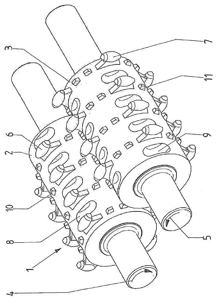
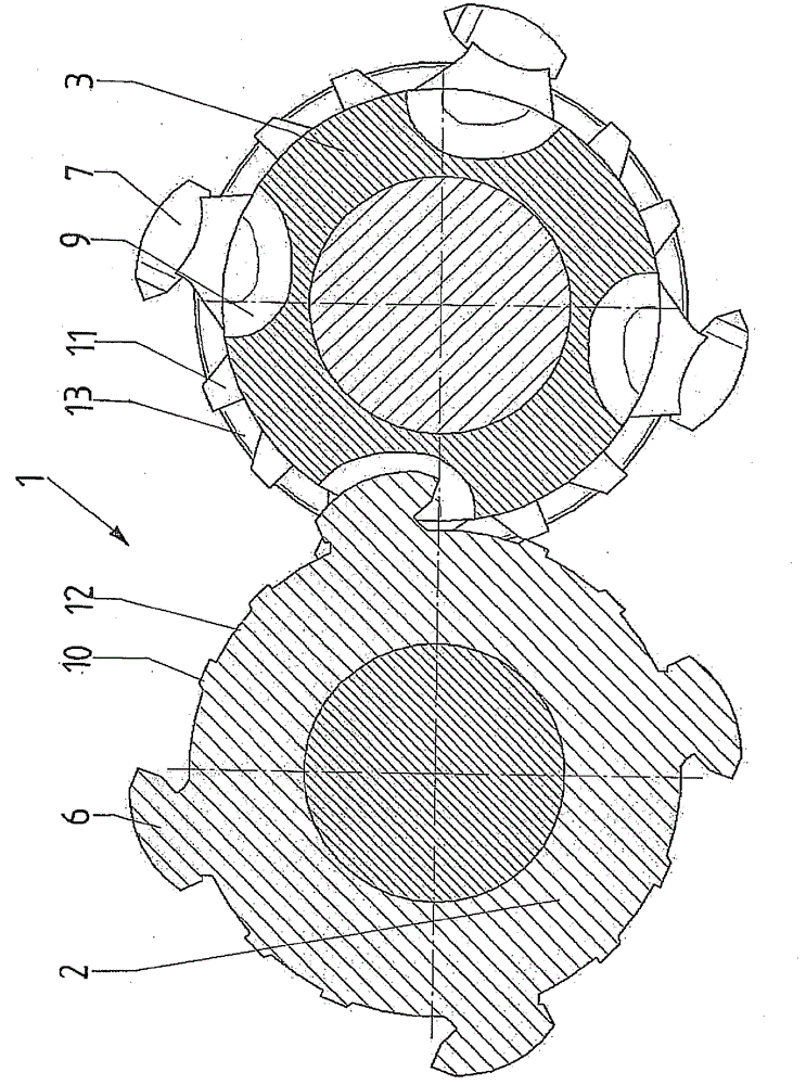
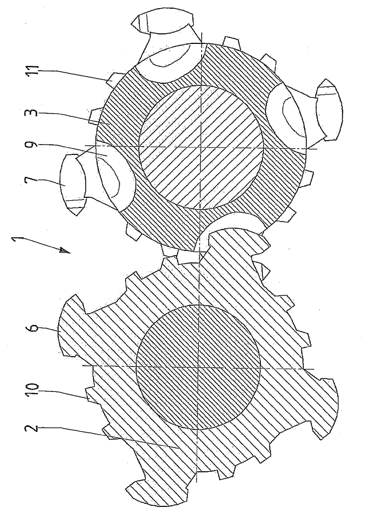
[0026] The elements of the main twin-roll mill 1 of the invention are shown in the drawings. This twin-roller mill has two rotatably mounted rollers 2 , 3 which are synchronously counter-driven by a motor. In this exemplary embodiment, the rollers 2 , 3 have on their end faces shaft ends which are mounted in the respective shredder housing and which correspond synchronously and oppositely to each other by means of a suitable drive in the form of a motor. Movement arrows 4, 5 are driven. The center axes of the two rollers 2 , 3 are aligned parallel to one another. Typically, such twin-roll mills are equipped with horizontally oriented rollers 2, 3, wherein the material to be crushed is brought in and introduced into the roller gap between the rollers 2, 3 from above, while the crushed Material is output from below.

[0027] Arranged on the surrounding surfaces of the rollers 2 , 3 are comminuting teeth 6 , 7 in the form of individual elements, which protrude radially in each...


PUM


Abstract

The invention relates to a twin roller crusher (1) with rollers (2, 3) that are rotatably mounted in a crusher housing and are motor-driven so as to turn synchronously in opposite directions, the center axes thereof being aligned in parallel to each other. Crusher teeth (6, 7) are arranged on the outer face of the crushers (2, 3), said teeth projecting beyond the lateral surfaces, every crusher tooth (6, 7) of a roller (2, 3) of the pair of rollers being associated with a pocket (8, 9) in the lateral surface of the other roller (2, 3) of the pair of rollers such that when the rollers (2, 3) rotate the crusher tooth (6, 7) is inserted into the pocket (8, 9).

Description

technical field [0001] The invention relates to a twin-roller pulverizer with rollers rotatably supported in a pulverizer housing and synchronously reversed driven by a motor, the central axes of the rollers pointing parallel to each other, wherein the Crushing teeth are arranged on the surrounding surface, and the crushing teeth protrude outside the surrounding surface. Background technique [0002] Twin-roll mills are well known and common especially in the field of crushing technology in the mining industry. In conventional twin-roll mills, the crushing of coarse rocks and the like takes place by means of two motor-driven rollers. The rollers are generally oriented horizontally, wherein the center axes of the rollers are oriented parallel to each other. The directions of rotation of the two rollers are opposite, precisely in such a way that, by the rotation of the rollers, the crushed material, usually supplied from above the roller gap, is introduced into the roller ga...

Claims


Application Information

Patent Timeline
IPC IPC(8): B02C4/08B02C4/30
CPCB02C4/08B02C4/30
Inventor M.迪克
Owner CRUSH SIZE TECH
Why Eureka
Try Eureka