Roller cutter with improved sealing

A technology of hob and retainer, which is applied in drilling equipment, earthwork drilling, drill bits, etc.

Inactive Publication Date: 2015-12-02
SANDVIK INTELLECTUAL PROPERTY AB
View PDF7 Cites 0 Cited by
  • Summary
  • Abstract
  • Description
  • Claims
  • Application Information

AI Technical Summary

Problems solved by technology

However, with this solution, refilling the hob with lubricant is problematic

Method used


Image

  • Roller cutter with improved sealing
  • Roller cutter with improved sealing
  • Roller cutter with improved sealing

Examples


Embodiment Construction

[0011] The characteristics and advantages of the present invention can be better understood by reading the following detailed description in conjunction with the accompanying drawings. In the accompanying drawings, similar reference numerals indicate similar components, and in the accompanying drawings:

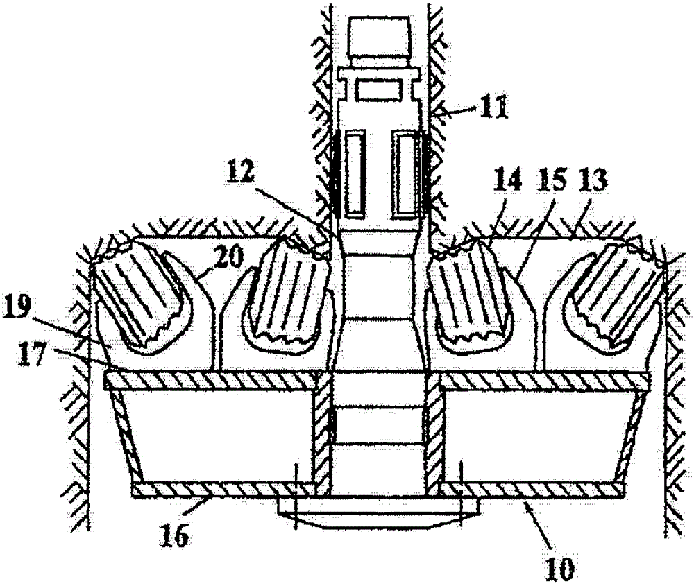
[0012] figure 1 Shows how the pilot hole 11 is drilled. The pilot hole is drilled between the upper ore bed and the lower ore bed using the existing method. The upper and lower ore beds are not shown in the figure. The pilot hole is drilled by the drill bit 10. Into. The drill bit 10 is connected to a driving rod 12, by means of the driving rod 12, the drill bit rotates and presses against the annular surface 13 around the pilot hole 11. The surface 13 thus defines the surface of the earth formation.

[0013] The present invention relates generally to formation drilling, but mainly to raise hole drilling. When drilling a raise hole, first drill a certain distance between the upp...


PUM


Abstract

A roller cutter (14) intended to be used at a drill head for rotary boring of the front of earth and rock formations, said roller cutter having a centre line (CL) and being provided with a hub (24) provided with rows of crushing members (29), at least one crushing member having its longitudinal axis at an angle relative to a normal to the centre line (CL), said hub being rotatable in relation to a shaft (33) having shaft spigots (34, 35), the roller cutter being provided with at least one seal retainer (38) arranged at an axial end of the hub in order to hold sealing means (37) in position, wherein the hub comprises at least one circumferential recess (44) positioned axially inward relative to a radially inward projecting flange (43) in the hub.

Description

Technical field [0001] According to the preamble of the independent claim, the invention relates to a drill bit hob for rotary drilling of the preceding formation or rock formation. Background technique [0002] US Patent No. 5,984,024 discloses a hob that includes improved sealing. It discloses that the sealing device is held in place by the sealing holder. The hob also includes a pressure relief hole, which includes a tapered plug, which is removed to refill the hob with lubricant such as grease or lubricating oil. However, with this solution, dirt will frequently invade the sealing device and collide with the O-ring of the seal, causing it to be misaligned, thereby reducing the sealing efficiency. [0003] US Patent No. 7,278,500 discloses another hob that includes improved sealing. It discloses that the sealing device is protected by a cover to prevent dirt from entering the inside of the hob. However, with this solution, refilling the hob with lubricant is problematic. Su...

Claims


Application Information

Patent Timeline
Patent Type & Authority Applications(China)
IPC IPC(8): E21B10/25
CPCE21B10/10E21B10/25
Inventor 约纳·洛伊卡宁斯蒂格-奥克·布罗隆德
Owner SANDVIK INTELLECTUAL PROPERTY AB
Why Eureka
Try Eureka