Spiral pressurization lock-in synchronism bone plate and application method thereof

A technology for synchronously locking and bone-synthesizing plates, applied in the direction of outer plates, fixators, and internal bone synthesis, which can solve problems such as time-consuming, labor-intensive fit, and disorderly buckling

Active Publication Date: 2015-12-09
山东康盛医疗器械股份有限公司
View PDF6 Cites 2 Cited by
  • Summary
  • Abstract
  • Description
  • Claims
  • Application Information

AI Technical Summary

Problems solved by technology

[0003] In the above pressurization process, because only the inner wall of the hole at the terminal end is provided with threads in the pressure hole, but there is no thread on the inner wall of the hole at the initial end, that is to say, the threads in the entire pressure hole are not continuous, that is, each The ring thread is disconnected, which will cause the thread of the screw head to rotate and pressurize at the initial end, and its thread will be hard pressed against the inner wall of the hole at the initial end without thread. This hard extrusion will hinder the screw on the one hand. When moving toward the terminal end, when the thread of the crushed screw head reaches the terminal end, it will have random buckling with the thread on the terminal hole wall, resulting in locking failure and slow, time-consuming and laborious pressurization process. Under the condition of fastening, it can meet the surgical requirements, but when the steel plate and screws need to be taken out after operation, random buckling will cause cold welding between the screw and the steel plate, making it difficult to take out the screw; second, if the screw is continuously forced to rotate, the thread on the screw may be The inner wall of the initial section is squeezed, causing the thread to be damaged and unable to cooperate with the inner thread of the terminal end, and it may also cause extrusion metal chips between the screw and the inner wall. If the metal chips fall on the bone, it will be very difficult to clean. At the same time It is also not conducive to the healing of bone gaps

Method used


Image

  • Spiral pressurization lock-in synchronism bone plate and application method thereof
  • Spiral pressurization lock-in synchronism bone plate and application method thereof
  • Spiral pressurization lock-in synchronism bone plate and application method thereof

Examples


Embodiment Construction

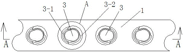
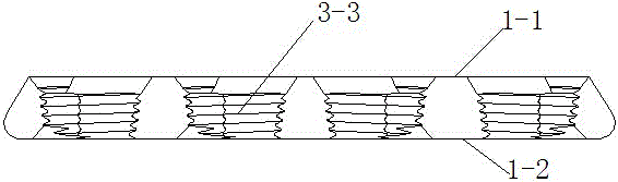
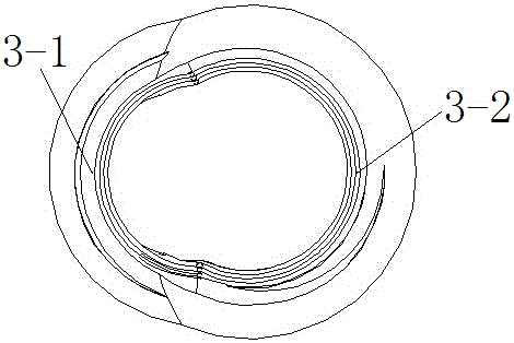
[0020] Figure 1-5 As an embodiment of the present invention, this embodiment is specifically described in conjunction with the accompanying drawings, including a bone plate body 1 and screws 2, the bone plate body 1 has a top surface 1-1 and a bottom surface 1-2 for the bone bone A group of oblong pressurized through-holes 3 arranged along the direction of its longitudinal axis are arranged on the bone plate body 1. The pressurized through-holes 3 can be straight holes or tapered holes. The pressurized through-holes 3 Connect the top surface 1-1 and the lower surface 1-2, one side of the pressurized through hole 3 is the initial end 3-1 for pressurization and the other side is the terminal end 3-2 for pressurization, the pressurized through hole 3 The upper part facing the top surface 1-1 has a groove to form a counterbore. The groove is a spherical expansion groove or a tapered groove formed by chamfering. 1 to the integral continuous thread 3-3 at the terminal end 3-2, the...


PUM


Abstract

The invention provides a spiral pressurization lock-in synchronism bone plate and an application method thereof. The bone plate comprises a bone plate body (1) and screws (2), wherein the bone plate body (1) is provided with a top surface (1-1) and a bottom surface (1-2) used for being connected with bones, a group of pressurization through holes (3) are formed in the bone plate body (1), the pressurization through holes (3) are connected with the top surface (1-1) and the bottom surface (1-2), an initial end (3-1) of the pressurization is arranged at one side of each pressurization through hole (3), a terminate end (3-2) of the pressurization is arranged at the other side of each pressurization through hole (3), integrally-continuous threads (3-3) are arranged on the inner walls of one or more pressurization through holes (3), each integrally-continuous thread (3-3) extends from the corresponding initial end (3-1) to the corresponding terminate end (3-2), and a thread (2-2) corresponding to the corresponding integrally-continuous thread (3-3) is arranged on the head portion (2-1) of each screw (2). According to the spiral pressurization lock-in synchronism bone plate and the application method thereof, in the pressurization and locking processes, no forced squeezing damage is caused, the mixed buckling phenomenon does not exist, no metal filing is generated, and time and labor are saved.

Description

technical field [0001] The invention relates to the field of medical instruments and equipment, in particular to a spiral pressurized locking synchronous bone plate and its application method. Background technique [0002] The Chinese patent discloses an invention patent with the application number 2011100714135 and the name is the locking pressurized bone setting device and its method of use. In order to reduce the cost of use, in this patented product, the body of the bone plate is provided with a pressure hole, the pressure hole extends from the initial end to the terminal end, and a thread is provided on the inner wall of the hole at the terminal end, and the screw head is provided with a threaded hole corresponding to the terminal end. When pressurized, the screw rotates and moves from the initial end to the terminal end, and the screw part of the screw pushes the bone to move toward the crack, and finally the thread of the screw head and the thread of the terminal end ...

Claims


Application Information

Patent Timeline
Patent Type & Authority Applications(China)
IPC IPC(8): A61B17/80A61B17/86
CPCA61B17/8014A61B17/8057A61B17/862A61B2017/564
Inventor 王郡
Owner 山东康盛医疗器械股份有限公司
Why Eureka
Try Eureka