Multi-face cascadable steering engine with position feedback center output shaft

A kind of steering gear, scalable technology, applied in manipulators, program-controlled manipulators, manufacturing tools, etc., can solve problems such as increased development costs, reduced stability and load, uneven weight distribution, etc. The effect of increased bearing capacity, simple and stable connection

Active Publication Date: 2015-12-09
SHENZHEN DEXTA ROBOTICS CO LTD
View PDF6 Cites 12 Cited by
  • Summary
  • Abstract
  • Description
  • Claims
  • Application Information

AI Technical Summary

Problems solved by technology

[0002] Existing models and servos for robots use single-sided eccentric output shafts, which are inconvenient during installation and use. The westward output shaft causes the output shaft to deviate from its geometric center, resulting in reduced accuracy, stability, and load bearing. This is especially true when multiple steering gears are cascaded and expanded. The single-sided output shaft makes the connecting surface of the steering gear very limited. It is difficult to directly connect two steering gears to each other at different angles. On the one hand, it increases the development cost and on the other hand reduces the space utilization
When multiple servos are cascaded, they must be connected in series through additional special-shaped parts, and cannot be connected directly
When the steering gear is loaded, because the output deviates from the collection center, it will cause uneven distribution of weight and increase the chance of damage to the steering gear
[0003] Due to the internal mechanical structure, the output shaft of the existing steering gear has a short extension length in the steering gear and low stability

Method used


Image

  • Multi-face cascadable steering engine with position feedback center output shaft
  • Multi-face cascadable steering engine with position feedback center output shaft
  • Multi-face cascadable steering engine with position feedback center output shaft

Examples


Embodiment Construction

[0024] In order to make the object, technical solution and advantages of the present invention clearer, the present invention will be further described in detail below in conjunction with the accompanying drawings and embodiments. It should be understood that the specific embodiments described here are only used to explain the present invention, not to limit the present invention.

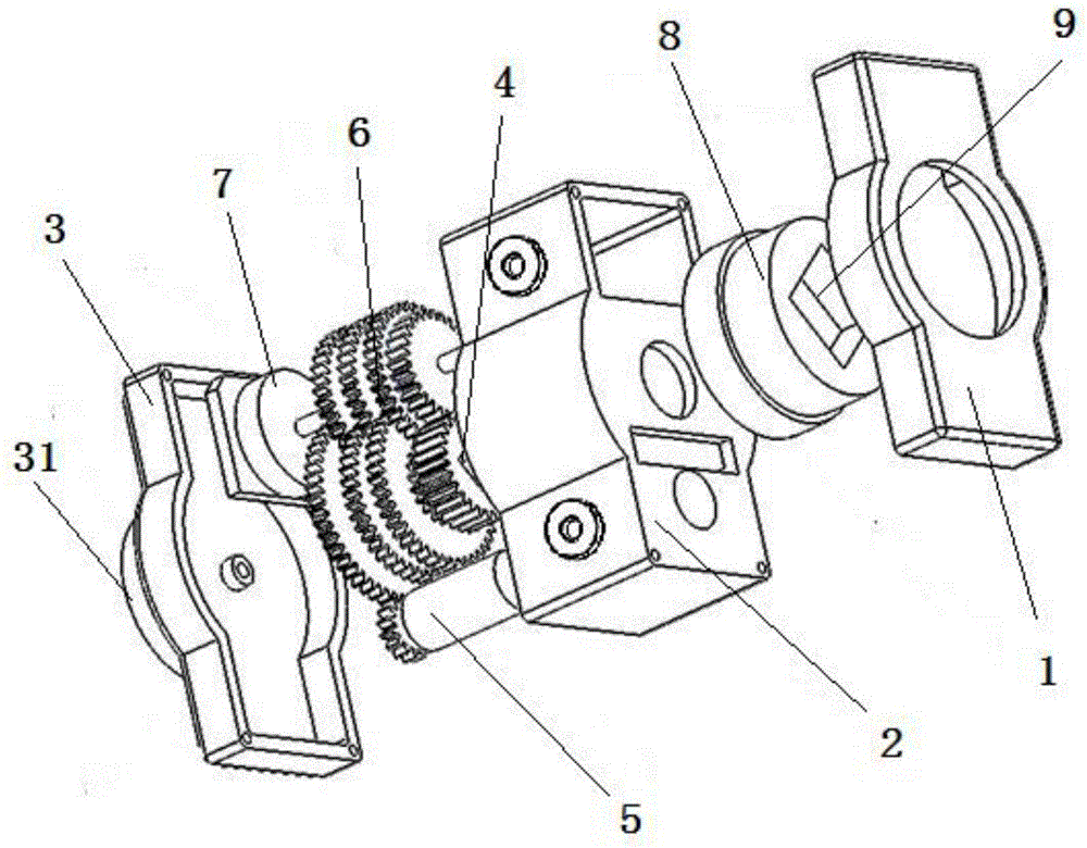
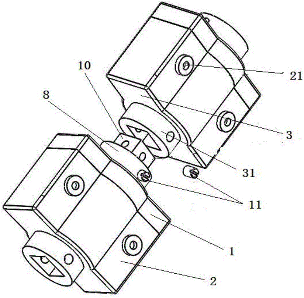
[0025] Such as figure 1 with Image 6 The shown multi-faceted cascadable steering gear with a center output shaft with position feedback includes a steering gear main body and a motor 5. The steering gear main body includes a top shell 1, a gear shell 2 and a The lower shell 3, the lower shell 3 is provided with a bottom shell connection port 31, the motor 5 is set and fixed in the gear shell 2, the center of the gear shell 2 is provided with an output shaft 4, and the output shaft 4 A reduction gear set 6 is provided, the output shaft of the motor 5 engages with the reduction gear set 6 through ...


PUM


Abstract

The invention discloses a multi-face cascadable steering engine with a position feedback center output shaft. The multi-face cascadable steering engine comprises a steering engine body and a motor. The steering engine body comprises a top shell, a gear shell and a lower shell. The lower shell is provided with a bottom outer shell connector. The motor is fixedly arranged in the gear shell. The output shaft is arranged at the central position of the gear shell, and is further provided with a reduction gear set. A rotation sensor which is in engaged linkage with the reduction gear set is further arranged in the gear shell. The top of the output shaft is connected with an output shaft connector, and connecting grooves of the same size are formed in the central position of the output shaft connector and the central position of the bottom outer shell connector. The output shaft connector can be in cascade connection with a bottom outer shell connector of the next steering engine through a quick-dismounting connecting piece, and meanwhile can be in cascade connection with the side face of the next steering engine through an angle connector. The structure is simple and geometric stability is good.

Description

technical field [0001] The invention relates to the technical field of steering gear, in particular to a multi-faceted cascadable steering gear with a central output shaft with position feedback. Background technique [0002] Existing models and servos for robots use single-sided eccentric output shafts, which are inconvenient during installation and use. The westward output shaft causes the output shaft to deviate from its geometric center, resulting in reduced accuracy, stability, and load bearing. This is especially true when multiple steering gears are cascaded and expanded. The single-sided output shaft makes the connecting surface of the steering gear very limited. It is difficult to directly connect two steering gears to each other at different angles. On the one hand, it increases the development cost and on the other hand reduces the space utilization. When multiple servos are cascaded, they must be connected in series through additional special-shaped parts, and c...

Claims


Application Information

Patent Timeline
Patent Type & Authority Applications(China)
IPC IPC(8): B25J17/02B25J9/18
Inventor 谷逍驰
Owner SHENZHEN DEXTA ROBOTICS CO LTD
Why Eureka
Try Eureka