Test tube rack storage and transportation device

A test tube rack and bottom plate technology, which is applied in the field of test tube rack storage and transportation devices, can solve problems such as inability to use instruments together, and achieve the effects of reducing the risk of overturning and pollution and preventing repeated taking.

Active Publication Date: 2017-03-01
SHANGHAI KEHUA LABORATORY SYSTEM CO LTD +1
View PDF6 Cites 0 Cited by
  • Summary
  • Abstract
  • Description
  • Claims
  • Application Information

AI Technical Summary

Problems solved by technology

However, this technology can only be used as a storage and transportation device for the test tube rack itself, and cannot be used in conjunction with the instrument

Method used


Image

  • Test tube rack storage and transportation device
  • Test tube rack storage and transportation device
  • Test tube rack storage and transportation device

Examples


Embodiment 1

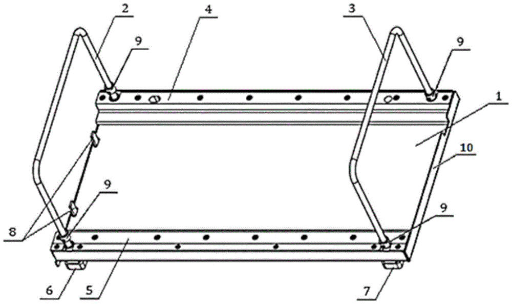
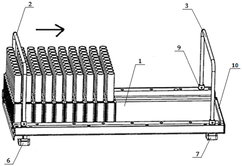
[0020] Such as Figure 1 ~ Figure 5 As shown, this embodiment includes: a bottom plate 1, a premise hand 2, a front support bar 6 corresponding to the premise hand 2, a rear handle 3, and a rear support bar 7 corresponding to the rear handle 3, wherein: the premise hand 2 The left and right ends of the rear handle 3 pass through the bottom plate 1 and are connected to the front support bar 6, and the left and right ends of the rear handle 3 pass through the bottom plate 1 and are connected to the rear support bar 7.

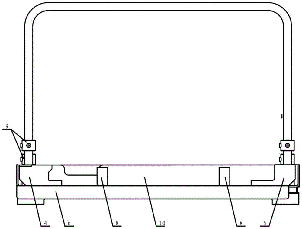
[0021] The front support bar 6 is provided with baffles 8, and the number of baffles 8 is preferably two, which are symmetrically distributed on the front support bar 6;

[0022] The bottom plate 1 includes a left guide bar 4, a right guide bar 5 and a channel corresponding to the baffle 8 of the front support bar 6.

[0023] The bottom plate 1 is provided with a folded edge 10 at the rear end.

[0024] The right side of the left guide strip 4 is an inclined inner groov...


PUM


Abstract

The invention discloses a test tube rack storage and transportation device, and belongs to the field of medical inspection equipment. The test tube rack storage and transportation device comprises a bottom plate, a front handle, a front supporting bar corresponding to the front handle, a rear handle and a rear supporting bar corresponding to the rear handle. The left and right ends of the front handle penetrate through the bottom plate to be connected with the front supporting bar. The left and right ends of the rear handle penetrate through the bottom plate to be connected with the rear supporting bar. The front supporting bar is provided with stop pieces. The bottom plate comprises a left guide bar, a right guide bar and channels corresponding to the stop pieces of the front supporting bar. The test tube rack storage and transportation device can reduce repeated test tube rack taking, improve operating efficiency and lower the risk that test tube racks topple or are contaminated.

Description

Technical field [0001] The invention relates to a technology in the field of medical inspection equipment, in particular to a test tube rack storage and transportation device. Background technique [0002] Medical testing centers such as hospitals and blood stations need to analyze the physiological indicators of a large number of liquid samples every day. The test tube containing the liquid sample is inserted into the test tube rack and then enters the testing instrument. As the test continues, the operator needs to take out the test tube racks one by one in the test instrument in time, and place them in the idle area one by one, waiting for the test tube rack to be recycled and reused. This process requires manual operation, which consumes a lot of time for the operator. At the same time, because the test tube is elongated, it is prone to overturning due to improper placement. [0003] Nowadays, the commonly used technology is to provide a set of independent test tube rack trans...

Claims


Application Information

Patent Timeline
Patent Type & Authority Patents(China)
IPC IPC(8): B65D6/08B65D25/00B65D25/24
Inventor 高玉莹苏涛
Owner SHANGHAI KEHUA LABORATORY SYSTEM CO LTD
Why Eureka
Try Eureka