Furrowing machine

A technology of trenchers and tractors, which is applied in the direction of digging/covering ditches, tillage implements, earth movers/shovels, etc. It can solve problems such as laborious, shallow and deep, and difficult to control, so as to achieve convenient operation and ensure The effect of deep consistency and reducing labor intensity

Active Publication Date: 2015-12-09
田开林
View PDF7 Cites 20 Cited by
  • Summary
  • Abstract
  • Description
  • Claims
  • Application Information

AI Technical Summary

Problems solved by technology

The applicant applied for the invention patent on December 30, 2013 and has obtained the invention patent right, which discloses a structure of a rear-mounted left-side ditcher. The ditcher includes a direct The L-shaped frame connected with the tractor rear connection frame, the gearbox is set on the frame, the output spline shaft of the gearbox is driven by the power mechanism of the tractor, and the roller cutter head, multiple blades, etc. are set on the spline shaft They are distributed on the outer periphery of the rotating drum cutter head. The operator drives a walking tractor to carry out ditching operations on the farmland. The operator needs to hold the walking tractor so that the blades on the drum cutter head are pressed against the soil of the farmland and cut into the soil. Implement the operation of digging the soil. When the above-mentioned ditching machine implements the operation of digging the soil, because the pressing force of the handle of the operator driving the walking tractor is different, the depth of the ditch is sometimes shallow and sometimes deep, and when walking on different When ditching is required on the ground, such as at the corner of the field, it is necessary to disassemble the L-shaped frame carrying the blade from the walking tractor, or lift the walking tractor to separate the blade from the ground. When holding the above-mentioned rear left ditcher, it is necessary to take into account the operation of the walking tractor and the contact between the blade of the ditcher and the ground. It is particularly laborious and difficult to control during the actual ditching operation.

Method used


Image

  • Furrowing machine
  • Furrowing machine
  • Furrowing machine

Examples


Embodiment Construction

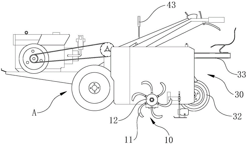
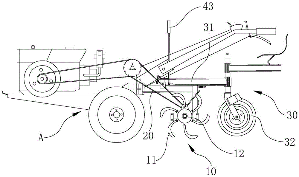
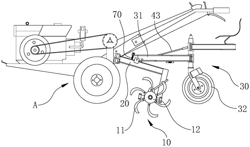
[0017] combine Figure 1 to Figure 11 , the present invention is further described:

[0018] A trencher, comprising a cutter assembly 10, the cutter assembly 10 includes a blade 11 and a cutter head seat 12 that fixes the blade 11, a drive mechanism connected to the cutter head seat 12 drives the cutter head seat 12 to rotate, and the cutter head seat 12 rotates Type is fixedly connected on the cutter assembly support 20, and the cutter assembly support 20 is connected with the tractor, and an adjustment mechanism is set between the tractor and the cutter assembly support 20, and the adjustment mechanism is used to adjust the height of the cutter head seat 12 up and down.

[0019] Utilize the adjustment mechanism arranged between the tractor A and the tool assembly bracket 20 to solve the disadvantage that the traditional trencher cannot adjust the cutter head seat 12 of the cutter assembly 10 up and down. The adjustment mechanism adjusts the cutter head seat 12 up and down T...


PUM


Abstract

The invention relates to the field of agricultural machines and particularly relates to a furrowing machine. The furrowing machine comprises a cutter assembly which comprises blades and a cutter disk base used for fixing the blades; a driving mechanism connected with the cutter disk base drives the cutter disk base to rotate; the cutter disk base is fixedly connected to a cutter assembly support in a rotating mode; the cutter assembly support is connected with a tractor; an adjusting mechanism is arranged between the tractor and the cutter assembly support and used for adjusting the height of the cutter disk base in the vertical direction; the adjusting mechanism arranged between the tractor and the cutter assembly support can effectively adjust the height of a cutter base in the vertical direction, and therefore the purpose that the blades are driven to make contact with or be separated from the ground can be achieved, the depth of the portions, entering soil, of the blades is set through the adjusting mechanism, furrowing depth consistency can be guaranteed, an operator only needs to hold the tractor in the hand, the adjusting mechanism enables the blades to be separated from the ground when furrowing operation is not needed, and therefore the tractor can be driven to run while the cutter assembly does not need to be disassembled; the furrowing machine is convenient to operate and can remarkably relieve the labor intensity of an operator.

Description

technical field [0001] The invention relates to the field of agricultural machinery, in particular to a ditching machine. Background technique [0002] The trencher can be used to excavate narrow and deep underground trenches in construction projects to bury underground drainage pipes, or for railways, post and telecommunications, urban construction and other departments to bury cables and pipelines, etc. It can also be used for orchards, vegetable gardens and other farmland environments. Fertilization, drainage, irrigation. Existing small-sized ditching machines for farmland ditching are mostly installed on walking tractors. The applicant applied for the invention patent on December 30, 2013 and has obtained the invention patent right, which discloses a structure of a rear-mounted left-side ditcher. The ditcher includes a direct The L-shaped frame connected with the tractor rear connection frame, the gearbox is set on the frame, the output spline shaft of the gearbox is d...

Claims


Application Information

Patent Timeline
Patent Type & Authority Applications(China)
IPC IPC(8): E02F5/08E02F5/14A01B33/02A01B33/08A01B33/10A01C5/06
Inventor 田开林
Owner 田开林
Why Eureka
Try Eureka