
Method of controlling a variator

A variable speed device, variable technology, applied in the direction of transmission, transmission control, components with teeth, etc., can solve the problem of reducing the efficiency of the transmission

Inactive Publication Date: 2015-12-09
GM GLOBAL TECH OPERATIONS LLC
View PDF5 Cites 2 Cited by
  • Summary
  • Abstract
  • Description
  • Claims
  • Application Information

AI Technical Summary

Problems solved by technology

Setting the clamping force too high will reduce the efficiency of the transmission

Method used


Image

  • Method of controlling a variator
  • Method of controlling a variator
  • Method of controlling a variator

Examples


Embodiment Construction

[0039] Those skilled in the art should understand that such as "up", "down", "up", "down", "top", "bottom" and the like are used to describe the accompanying drawings, and do not represent limitations on the scope of the present invention. Defined by the appended claims.And then, the present invention can be described in the mode of function and / or logic module parts and / or various processing steps herein.Should be appreciated that this module parts can comprise any number of hardware, software and / or firmware components configured to perform specific functions.

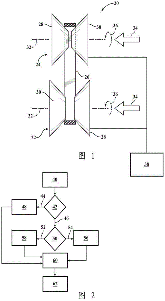
[0040] Referring to the drawings, wherein like reference numerals designate like parts throughout the several views, the transmission is generally at figure 1 is shown at 20 in . The speed change device 20 is a mechanical device that changes an operating parameter, or a mechanical device that changes an operating parameter of another device. The transmission 20 may include any device that has a first member and a s...


PUM


Abstract

A method of controlling a variator that requires clamping pressure between a first component and a second component to transfer torque therebetween, such as a continuously variable transmission, includes calculating a theoretical clamping pressure, and multiplying the theoretical clamping pressure by a multiplier to define a commanded clamping pressure. The multiplier includes a value that is variable between a minimum multiplier value and a maximum multiplier value. The value of the multiplier is based on current operating conditions of the variator. The commanded clamping pressure is applied to the first component and the second component to generate friction and transfer torque between the first component and the second component.

Description

technical field [0001] The present invention generally relates to a method of controlling a transmission, such as a continuously variable transmission, that requires clamping pressure between a first member and a second member to transmit torque between the first member and the second member. Background technique [0002] A speed change device is a mechanical device that changes an operating parameter, or a mechanical device that changes the operating parameter of another device. An example of a transmission device is a continuously variable transmission (CVT), which is a mechanical power transmission device for transmitting torque from an engine to an output such as a wheel. A CVT can continuously change between an infinite number of gear ratios. Typically, a transmission includes a first component, such as a drive belt, that is compressed by a second component, such as between two sheaves of a variable width pulley, to transmit torque between them. [0003] A clamping fo...

Claims


Application Information

Patent Timeline
IPC IPC(8): F16H61/662
CPCF16H61/66272F16H9/125F16H2061/66218F16H2061/66277
Inventor Z.J.张J.B.布拉德利J.B.伯奇J.E.马拉诺
Owner GM GLOBAL TECH OPERATIONS LLC
Learn More