
Dehumidification device and operation method therefor

A working method and humidity technology, applied in heating methods, lighting and heating equipment, heating and ventilation control systems, etc., can solve problems such as compressor overload, efficiency reduction, and no public solution, to prevent overload, prevent ice, The effect of improving energy efficiency

Active Publication Date: 2017-05-31
COWAY CO LTD
View PDF7 Cites 3 Cited by
  • Summary
  • Abstract
  • Description
  • Claims
  • Application Information

AI Technical Summary

Problems solved by technology

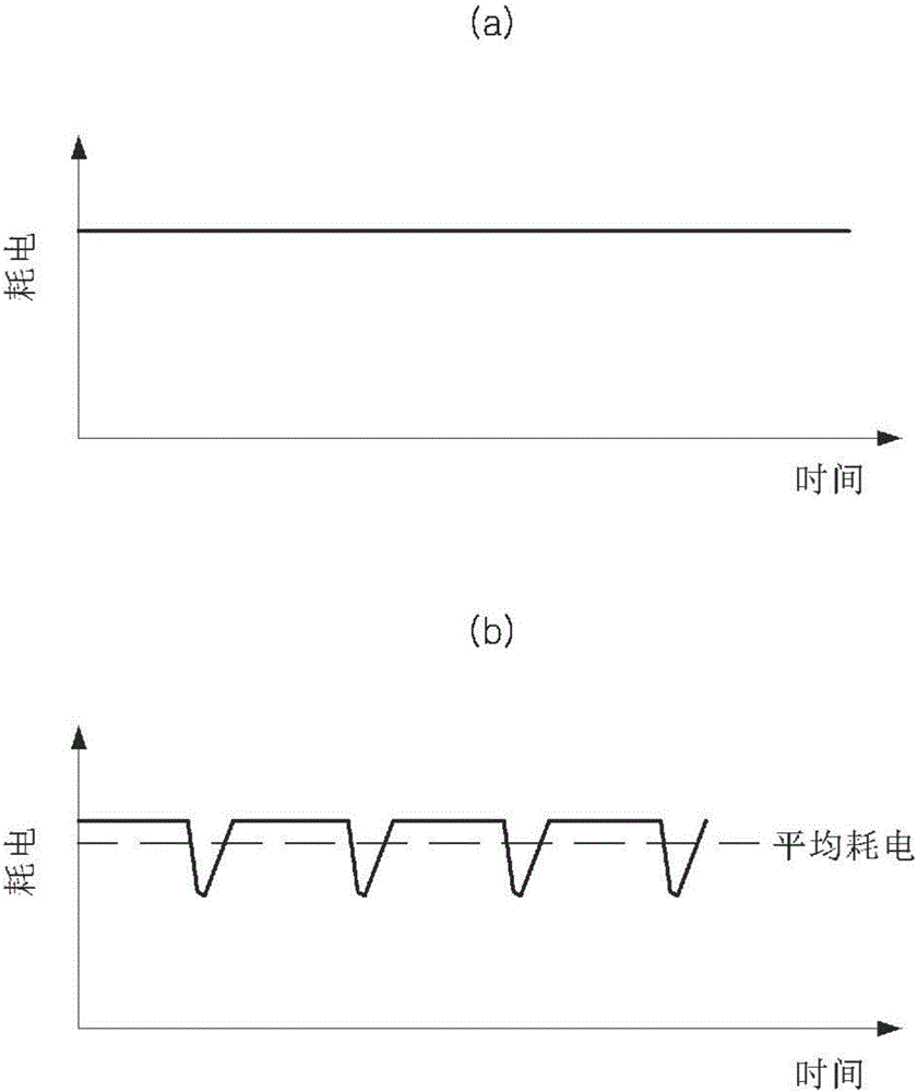
[0005] On the contrary, in a dehumidifier using a variable compressor, although the rotation speed of the variable compressor can be changed in consideration of the humidity of the air, the rotation speed of the variable compressor is adjusted stepwise when the air humidity is within the target humidity range. rotation speed, so there is a limit to improving energy efficiency while maintaining the dehumidification performance of the dehumidifier
[0006] In addition, the existing dehumidifiers can generate frost on the heat exchanger in a low-temperature and low-humidity environment. Although the humidity is low, the rotation speed of the compressor cannot be reduced, so there is a problem of reduced efficiency.
In addition, the existing dehumidifier may overload the compressor in a high-temperature and high-humidity environment
[0007] The following patent document 1 relates to a device having a dehumidification function and an air purification function and a control method thereof, but does not disclose a solution to the above-mentioned problems

Method used


Image

  • Dehumidification device and operation method therefor
  • Dehumidification device and operation method therefor
  • Dehumidification device and operation method therefor

Examples


Embodiment Construction

[0030] Hereinafter, preferred embodiments of the present invention will be described in detail with reference to the accompanying drawings so that those skilled in the art can easily carry out the present invention. However, when describing the preferred embodiments of the present invention in detail, if it is considered that the detailed description of related known functions or structures may unnecessarily obscure the gist of the present invention, the detailed description will be omitted. In addition, the same symbols are used throughout the drawings for parts having similar functions or actions.

[0031] In addition, if it is described in the overall specification that a certain part is "connected" to other parts, it includes not only the case of "direct connection" but also the case of "indirect connection" with other elements interposed therebetween. In addition, "include" a certain constituent element, if there is no explicit statement to the contrary, it means to inclu...


PUM


Abstract

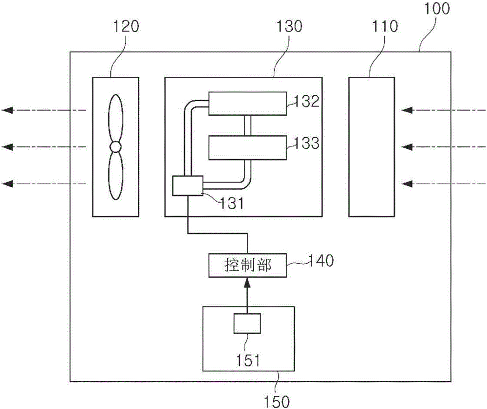
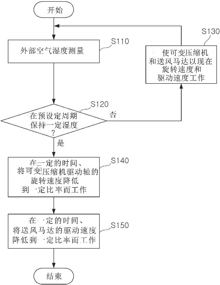
A dehumidification device and an operation method therefor are disclosed. The dehumidification device can comprise: an air blowing part for causing external air to flow therein by using an air blowing fan and an air blowing motor operating the air blowing fan so as to form an air flow; a variable compressor for controlling the amount of a refrigerant gas to be compressed, by varying the rotation speed of a drive shaft; a condenser for liquefying the refrigerant gas compressed by the variable compressor; a heat exchanger for cooling the air, which has flowed in by the air blowing part, by vaporizing the refrigerant gas liquefied by the condenser; and a control unit for controlling the rotation speed of the drive shaft of the variable compressor at every predetermined period.

Description

technical field [0001] The present application relates to a dehumidification device and its working method. Background technique [0002] A dehumidification device for dehumidifying air generally removes air moisture using a refrigeration cycle including a compressor, a condenser, and a heat exchanger. That is, moisture can be removed by condensing water vapor contained in the air into water in a heat exchanger. [0003] Here, the compressor may be constituted by a fixed compressor operating at a fixed rotational speed, or a variable compressor whose rotational speed is variable. [0004] In a dehumidifier using a fixed compressor, the fixed compressor is operated at a fixed rotation speed until the air humidity reaches a target humidity range, and the operation of the fixed compressor is stopped when the target humidity range is reached. [0005] On the contrary, in a dehumidifier using a variable compressor, although the rotation speed of the variable compressor can be c...

Claims


Application Information

Patent Timeline
Patent Type & Authority Applications(China)
IPC IPC(8): F24F3/14F24F11/02F24F11/053F24F11/76
CPCF24F3/14F24F11/89F24F11/76
Inventor 洪铉轸韩昌洙李赞熙崔荣光许诚桓
Owner COWAY CO LTD
Learn More