Multistage integrated hydrodynamic cyclone separator

A cyclone separator and fluid power technology, which is applied in the direction of separating sediments by centrifugal force, can solve the problems of poor separation effect, and achieve the effects of centralized dredging, improved stability, and improved removal efficiency

Inactive Publication Date: 2012-06-27
BEIJING UNIVERSITY OF CIVIL ENGINEERING AND ARCHITECTURE
7 Cites 18 Cited by

AI-Extracted Technical Summary

Problems solved by technology

[0005] The purpose of the present invention is to provide a practical multi-stage integrated hydrodynamic cyclone separator with optimized treat...

Method used

Described conical deflector 10 is inclined downwards to its center from its outside, makes the space of the one-stage cone segment separation chamber 2 of conical deflector 10 inner side be big and small, become a conical space, This can not only improve the swirling effect and stability, but also guide the rainwater runoff that flows into the cylindrical deflector 9 and spirals downward to the secondary column separation chamber 3. At the same time, this configuration design, in the While improving the swirl effect, the separation space of the secondary column separation chamber 3 and the tertiary column separation chamber 4 is increased. In addition, the floating matter separated in the rainwater stays on the top of the first-level cone section separation chamber 2, that is, the inside of the columnar deflector 9 and the floating matter storage chamber 1, which can prevent the floating matter from affecting the conical deflector. Swirl effects within 10 are affected. In addition, the bottom of the conical deflector 10 is designed so that the floating matter and fine particles in the rainwater runoff moving downward spirally form an upward backflow, which is in the lower part of the first cone segment separation chamber 2, that is, in the conical Inside the deflector 10, the fine particles and floating objects form a backflow when approaching the outlet of the first-stage cone section separation chamber 1, and finally stagnate near the center of the swirling fluid, thereby realizing the retention of fine particles and floating objects.
Described helical deflector 11 is arranged on the below of the tangential interface of tangential water inlet pipe 7 and cylindrical deflector 9, is connected with the inwall of conical deflector 10, can restrict fluid trajectory, improve vortex flow type, reduce flow field disturbance, and guide the stable flow of fluid, so the stability of fluid rotation at high flow rate is improved.
Described inclined baffle 12 is positioned at the top of the bottom outlet of described conical deflector 10, can prevent the generation of short-flow phenomenon, and inclined baffle 12 is inclined downwards from its outside to its center, and is arranged at the bottom There is a skirt 12.1, which can control the outflow of the liquid in the secondary column se...

Abstract

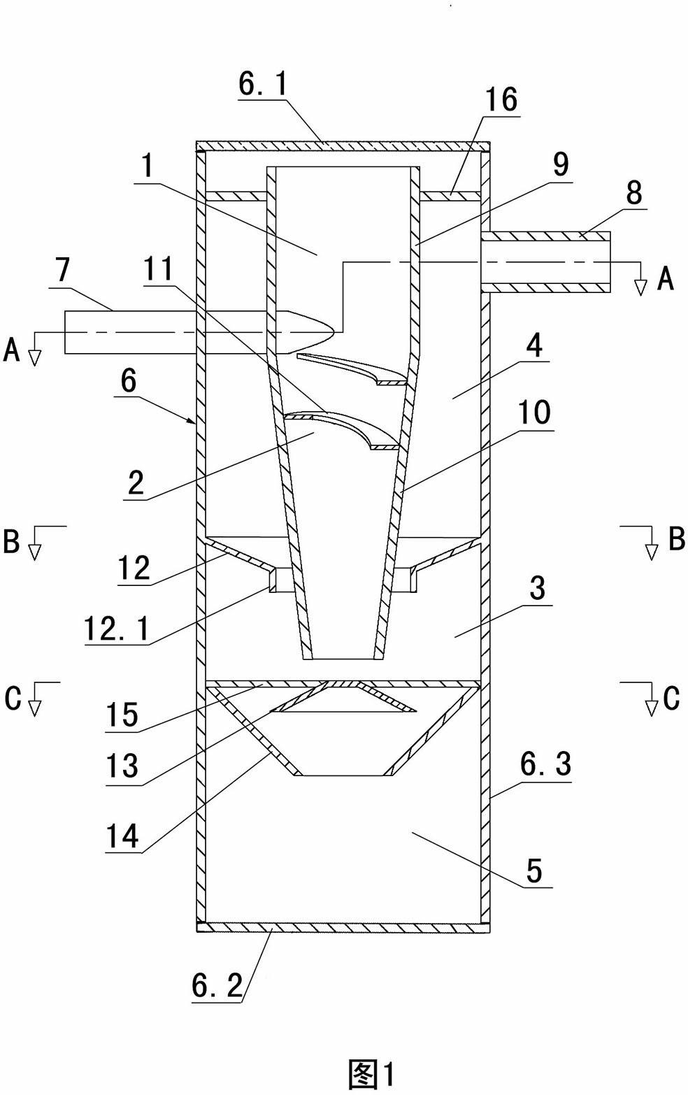
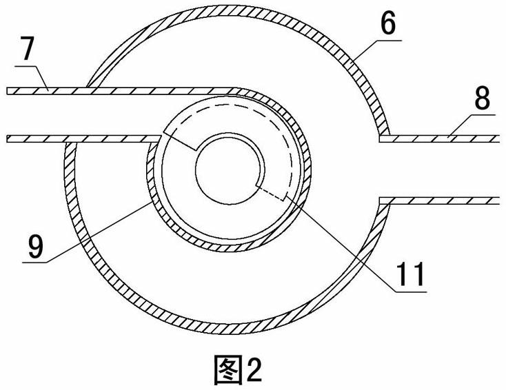
The invention provides a multistage integrated hydrodynamic cyclone separator. The cyclone separator comprises a cylindrical shell and a tangential inlet pipe and an outlet pipe connected with the cylindrical shell; the cylindrical shell comprises a top cover, a bottom plate and a side wall, wherein, the top cover is a detachable cover plate or a partially perforated cover plate; a cylindrical guide plate is arranged at the center of the upper part in the cylindrical shell and is connected with the side wall of the cylindrical shell through a cylindrical guide plate support frame, the lower end of the cylindrical guide plate is connected with a tapered guide plate which has a larger diameter at its upper part and a smaller diameter at its lower part, a separation chamber inclined baffle plate is arranged in a cavity between the tapered guide plate and the side wall, and a sediment storage chamber separation baffle plate is provided below the tapered guide plate and on the side wall of the cylindrical shell. The cyclone separator has three-stage separation chambers which are integrated into one, so the cyclone separator provided in the invention has an improved removal effect on particles and enhanced effective treating ability compared to conventional cyclone separators.

Application Domain

Centrifugal force sediment separation

Technology Topic

EngineeringCyclone +3

Image

  • Multistage integrated hydrodynamic cyclone separator
  • Multistage integrated hydrodynamic cyclone separator
  • Multistage integrated hydrodynamic cyclone separator

Examples

  • Effect test(1)

Test Example

[0044] Application examples of the present invention in simulated rainstorm pollution runoff control: the cylindrical deflector in the present invention has an inner diameter of 250mm and a height of 250mm; the cone angle of the conical deflector is 7°, the height is 500mm, and the upper opening diameter is 250mm; The inclination angle of the spiral deflector is 11°, the width is 60mm, and the height is 250mm; the inclination angle of the semi-isolated inclined baffle is 45°, the height is 150mm, and the upper mouth diameter is 450mm; the inclination angle of the resuspension control cover is 30°, and the height The diameter of the upper mouth is 50mm; the inclination angle of the inclined baffle is 23°, the height is 50mm, the upper mouth diameter is 550mm, the bottom skirt diameter is 220mm, the height is 30mm; the tangential inlet pipe diameter is 65mm, and the outlet pipe diameter Is 100mm. Separation effect: when the inlet median diameter D50 varies within 45-61μm, the removal efficiency of solid particles with a particle size of 0-45μm is 25.79-38.66%, and the removal of solid particles with a particle size of 45-125μm The efficiency is 48.41~69.18%, and the removal efficiency of solid particles with a particle size of 125μm or more reaches 86.31~96.80%.

PUM

PropertyMeasurementUnit
Slope5.0 ~ 15.0deg
Slope0.0 ~ 15.0deg
Cone angle5.0 ~ 10.0deg
tensileMPa
Particle sizePa
strength10

Description & Claims & Application Information

We can also present the details of the Description, Claims and Application information to help users get a comprehensive understanding of the technical details of the patent, such as background art, summary of invention, brief description of drawings, description of embodiments, and other original content. On the other hand, users can also determine the specific scope of protection of the technology through the list of claims; as well as understand the changes in the life cycle of the technology with the presentation of the patent timeline. Login to view more.

Similar technology patents

Adaptive correction method for color gray-scale image of display

ActiveCN102629466AGuaranteed display qualitySmall footprintCathode-ray tube indicatorsImage propertiesCorrection method
Owner:NANJING JUSHA DISPLAY TECH

Classification and recommendation of technical efficacy words

  • Easy to install and control
  • Small footprint

Fault diagnosis and rehabilitation center for train wheel sets

InactiveCN102706572AAvoid cumbersome wiringEasy to install and controlRailway vehicle testingAutomotive engineeringVibration sensor
Owner:BEIJING HAIDONGQING ELECTRICAL & MECHANICAL EQUIP

Wind driven engine with combined wind cups and blades

InactiveCN1847645ASimple control technologyEasy to install and controlWind motor controlRenewable energy generationWind drivenWind force
Owner:王跃

Anti-punching oblique anchor bolt

InactiveCN110080395AEasy to install and controlEasy to installBuilding material handlingMaterial consumptionDuctility
Owner:XI'AN UNIVERSITY OF ARCHITECTURE AND TECHNOLOGY

Absorber sealing quality detection device

PendingCN107991112AAvoid wiringEasy to install and controlMachine part testingRailway vehicle testingData transmissionInfrared
Owner:NANYANG XIJIAN AUTOMOBILE SHOCK ABSORBER

Multi-node control system

InactiveCN103116293AReduce the number of wiresEasy to install and controlProgramme controlComputer controlElectronic control unitVoltage
Owner:HANGZHOU SANHUA RES INST CO LTD
Why Eureka
Try Eureka