Control mechanism provided with at least one adjusting arm

A technology of servo drive and arm adjustment, applied in the field of servo drive, can solve problems such as injury, and achieve the effect of reducing the acting force and moment

Active Publication Date: 2007-12-19
JULIUS BLUM GMBH
View PDF0 Cites 23 Cited by
  • Summary
  • Abstract
  • Description
  • Claims
  • Application Information

AI Technical Summary

Problems solved by technology

Adjustment arm biased by spring means at the above critical moment, where no flap is hinged to the adjustment arm, may cause serious injury

Method used


Image

  • Control mechanism provided with at least one adjusting arm
  • Control mechanism provided with at least one adjusting arm
  • Control mechanism provided with at least one adjusting arm

Examples


Embodiment Construction

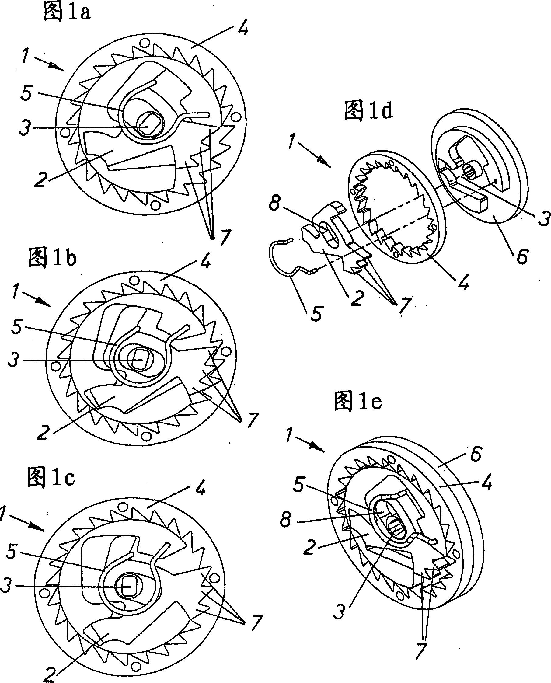
[0031] 1 a - 1 e show different views of an exemplary braking or immobilizing device 1 . 1a-1c show the chronological sequence of the embedding process if a threshold value for the rotational speed of the rotational arm, which is not shown for the sake of clarity, is exceeded. FIG. 1 a shows the unlocked state of the braking or immobilizing device 1 , FIG. 1 b shows the moment of the engagement process and FIG. 1 c shows the locked state. As is evident in particular from the exploded view in FIG. 1 d , the braking or locking device is designed as a ratchet lock with ratchet teeth. A receiving element 6 is arranged concentrically to the bearing shaft 3 of the adjusting arm. The receiving element 6 is designed such that the second coupling element 4 can be pushed onto it. In the exemplary embodiment shown, the second clutch element 4 is designed as an internal toothed ring. The first clutch element 2 forms the counter part of the inner toothed ring 4 . The first clutch eleme...


PUM


Abstract

The invention relates to an actuating device for moving a flap of a piece of furniture, including at least one actuating arm for moving the flap, a base member on which the actuating arm is pivotally arranged, and a spring device able to act upon the actuating arm. An assembly securing device for the vacant actuating arm, which has not yet been fitted with a flap, includes a braking device which limits the opening speed of the vacant actuating arm.

Description

technical field [0001] The invention relates to a servo drive comprising at least one adjusting arm, in particular for driving a furniture flap, a base body on which the adjusting arm is rotatably supported, and a spring device for biasing the adjusting arm. Background technique [0002] Actuating drives of this type are usually fastened to the side walls of the furniture body and serve to move a furniture flap hinged on an adjusting arm from an open position to a closed position or vice versa. Depending on the size and weight of the furniture flap, the servo drive is equipped with a spring device which in part exerts an extremely high biasing force on the adjusting arm in order to be able to move even heavy furniture flaps. The critical moment that occurs during the assembly of the flap during transport and when switching the flap is due to the fact that the lighter actuating arm is accelerated in a bullet-like manner by means of the biased spring arrangement. For this rea...

Claims


Application Information

Patent Timeline
Patent Type & Authority Applications(China)
IPC IPC(8): E05F1/10E05F5/00
CPCE05Y2201/242E05Y2900/20E05Y2201/224E05Y2201/266E05Y2201/26E05F5/00E05F1/1058E05Y2201/21E05Y2201/416E05Y2600/00E05Y2800/40
Inventor F·杜巴赫C·奥曼
Owner JULIUS BLUM GMBH
Why Eureka
Try Eureka