Ball endmill

a ball endmill and ball mill technology, which is applied in the direction of workpieces, milling equipment, metal-working equipment, etc., can solve the problems of inability to achieve a sufficiently high machining efficiency, the above-described ball endmill is not capable of machining a workpiece at a high speed or with a large cut depth, etc., to achieve a higher speed, improve machining efficiency, and increase the depth

Inactive Publication Date: 2007-07-26
OSG +1
View PDF11 Cites 23 Cited by
  • Summary
  • Abstract
  • Description
  • Claims
  • Application Information

AI Technical Summary

Benefits of technology

[0010] In the ball endmill defined in claim 1 in which the ball-nosed end cutting edges are provided in the distal end portion of the tool body, since the tool body is constituted, at least at the part providing each of the ball-nosed end cutting edges, by the hard sintered body, the ball endmill is capable of performing a machining operation at a higher speed with a larger depth of cut, as compared with a ball endmill whose ball-nosed end cutting edges are constituted by cemented carbide. Thus, the present ball endmill provides an advantage of improving a machining efficiency.
[0011] Further, the rake face of each of the ball-nosed end cutting edges, which are provided in the distal end portion of the tool body, is defined by the spiral gash, so that each of the ball-nosed end cutting edges is defined by a circular arc, as seen in a distal end view perpendicular to the axis of the tool body, which is convex in a direction of rotation of the tool body (i.e., in a direction of cutting action of the tool). Owing to this construction, a cutting resistance acting on the ball endmill can be made smaller than in a conventional ball endmill in which each ball-nosed end cutting edge is defined by a straight line as seen in the distal end view. The reduction in the cutting resistance permits the ball endmill to perform a machining operation at an increased speed with an increased depth of cut, thereby leading to an improvement in the machining efficiency.
[0012] Further, the helix angle of each of the spiral gashes is in the range from about 10° to about 30°. In general, an increase in the helix angle of each spiral gash leads to easy chipping of the cutting edge and the consequent reduction in the tool life. However, in the present invention, since the helix angle is not larger than about 30°, it is possible to prevent the chipping of the cutting edge and accordingly to prolong the tool life.
[0013] On the other hand, a reduction in the helix angle of each spiral gash leads to reduction in the cutting performance of each ball-nosed end cutting edge, making it impossible to obtain a sufficiently high machining efficiency. However, in the present invention, since the helix angle is not smaller than about 10°, it is possible to prevent the reduction in the cutting performance of each ball-nosed end cutting edge and accordingly to obtain a sufficiently high machining efficiency.
[0014] Further, the non-gashed central area in which the ball-nosed end cutting edges or spiral gashes are absent has a size in a range from about 0.03R to about 0.1R relative to the ball nose radius R of the ball endmill. In this non-gashed central area, i.e., an end-cutting-edge absence area, a rotational speed is slow, and a large friction is generated. Therefore, if a thickness of the non-gashed central area is excessively reduced, the tool body is likely to be easily broken at the non-gashed central area due to reduction in rigidity of the tool body at the non-gashed central area. However, in the present invention, since the non-gashed central area in which the spiral gashes do not exist is not smaller than about 0.03R relative to the ball nose radius R of the ball endmill, it is possible to prevent breakage of the tool body at the non-gashed central area and accordingly to prolong the tool life.
[0015] On the other hand, if the thickness of the non-gashed central area is excessively increased, the friction acting between the non-gashed central area and a machined surface of the workpiece is increased whereby a smoothness of the machined surface is reduced, so that a satisfactory surface finish can not be obtained. However, in the present invention, since the non-gashed central area is not larger than about 0.1R relative to the ball nose radius R of the ball endmill, it is possible to prevent reduction in the smoothness of the machined surface and accordingly to obtain a satisfactory surface finish.

Problems solved by technology

However, the above-described ball endmill is not capable of machining a workpiece at a high speed or with a large depth of cut, since a cutting resistance acting on the ball endmill is large due to its construction in which each of the cutting edges extends straight as seen in an end view perpendicular to an axis of the tool body.
That is, there is a problem that a sufficiently high machining efficiency can not be obtained by the construction in which the plate members each provided by the two-layered body are brazed to the corner portions of the tool body.

Method used


Image

  • Ball endmill
  • Ball endmill
  • Ball endmill

Examples


Embodiment Construction

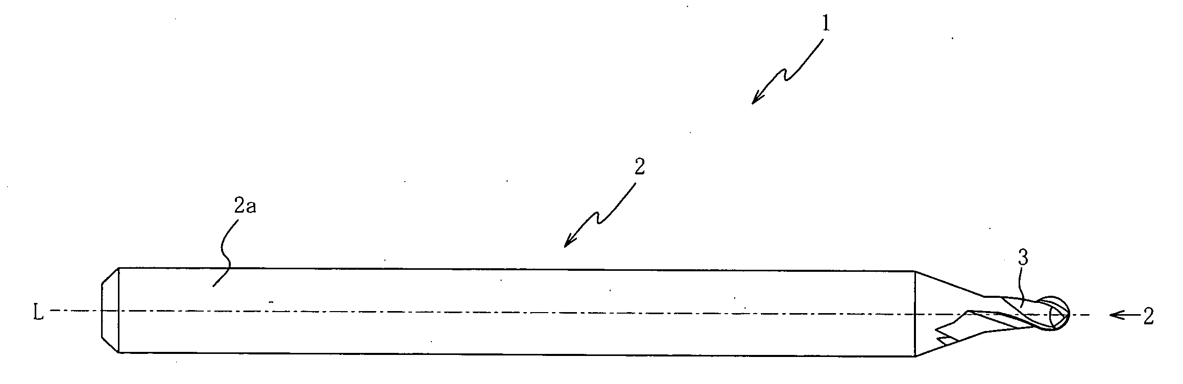
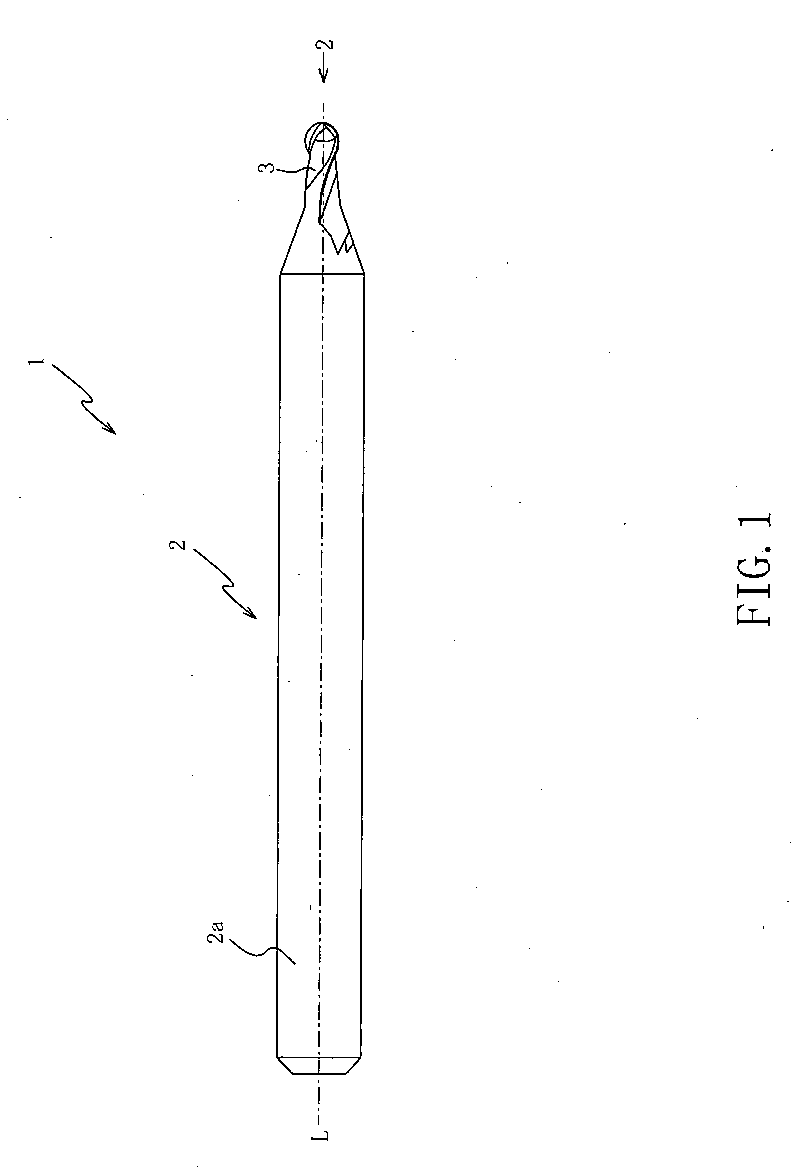
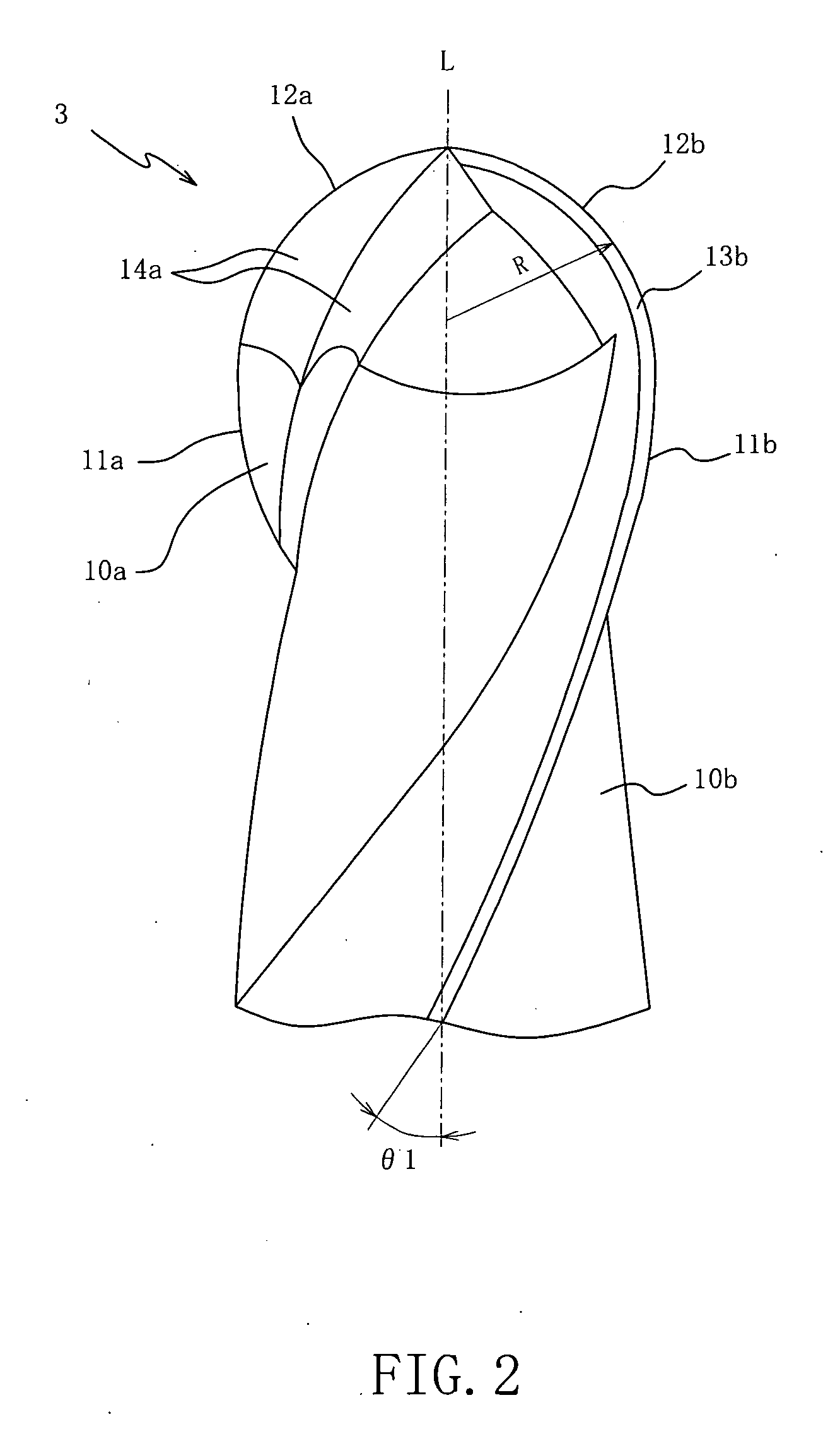
[0036] Hereinafter, a preferred embodiment of the present invention will be described with reference to the drawings. FIG. 1 is a front elevational view of a multi-flute ball endmill 1 (hereinafter simply referred to as “ball endmill”) according to the embodiment of the invention. FIG. 2 is an enlarged view of a distal end portion (right-side portion as seen in FIG. 1) of the ball endmill 1. FIG. 3 is a side view of the ball endmill 1 as seen in a direction of arrow II of FIG. 1. Referring first to FIGS. 1-3, there will be described a whole construction of the ball endmill 1.

[0037] The ball endmill 1 is principally constituted by a tool body 2 having an axis L and including a blade portion 3 and a shank portion 2a that are coaxial with each other. This ball endmill 1 is to be used for cutting or machining a workpiece so as to finish a free curved surface or rounded corner section surface of a die or molding. In a machining operation, the ball endmill 1 is attached to a machine tool...


PUM


Abstract

A ball endmill includes a cylindrical tool body that is to be rotated about its axis, ball-nosed end cutting edges located in an axially distal end portion of the tool body and describing a semi-spherical-shaped locus during rotation of the tool body, and spiral gashes located in the axially distal end portion of the tool body and defining rake faces of the respective ball-nosed end cutting edges. The tool body is made, at least at its part providing each ball-nosed end cutting edge, of a hard sintered body. Each ball-nosed end cutting edge is inclined with respect to the axis by a helix angle in a range from about 10° to about 30°. The tool body has, in its distal end, a non-gashed central area in which the spiral gashes do not exist. A ratio of a size of the non-gashed central area to a ball nose radius is in a range from about 0.03 to about 0.1.

Description

TECHNICAL FIELD [0001] The present invention relates to a ball endmill, and more particularly to such a ball endmill that is capable of exhibiting a machining 14BACKGROUND ART [0002] In an operation performed by a machine tool such as machining center for profile-machining of a die or mold, it is common that a ball endmill made of cemented carbide is used. Where the ball endmill is used to machine a workpiece that is made of a material hardened for a longer service life, cutting blades of the endmill are easily worn whereby its tool life is shortened. The tool life could be increased, for example, by reducing a depth of cut in the machining operation. However, the reduction in the depth of cut inevitably increases a length of time required for the machining operation, thereby resulting in reduction in the machining efficiency. In recent years, for reducing the wear on the cutting blades without reducing the machining efficiency, there is used a ball endmill whose cutting blades are ...

Claims


Application Information

Patent Timeline
Patent Type & Authority Applications(United States)
IPC IPC(8): B26D1/12B23C5/10
CPCB23C5/1009B23C2210/03B23C2210/0407Y10T407/1946B23C2222/28B23C2226/125B23C2226/315B23C2210/0485
Inventor NAGAI, TAMOTSU
Owner OSG
Why Eureka
Try Eureka