Mud pipe and design method for self-floating armored mud pipe

A design method and technology for sludge discharge pipes, applied in the direction of pipes/pipe joints/fittings, hoses, pipes, etc., can solve problems such as service life, product transportation cost gap, mismatch, etc., to achieve outstanding substantive characteristics and improve buoyancy. , the effect of ensuring the carrying capacity

Active Publication Date: 2015-12-09
姜考成
View PDF6 Cites 4 Cited by
  • Summary
  • Abstract
  • Description
  • Claims
  • Application Information

AI Technical Summary

Problems solved by technology

However, due to the product defects in the self-floating mud discharge rubber pipe itself, there are the following deficiencies: the first is that although the self-floating mud discharge rubber pipe has certain bending properties, it is used as a mud discharge elbow to play a role. There are still obvious inherent deficiencies in the function of adjusting the direction of the mud discharge pipeline, especially when it is used in conjunction with the bundled floating metal mud discharge pipe; the second is that the self-floating mud discharge rubber pipe passes through the hose. The technical solution of adding organic adhesive and wear-resistant steel ring to the innermost layer is to achieve the purpose of improving the wear resistance of the rubber pipe itself. However, compared with the metal composite mud discharge pipe with good wear resistance, the price, service life, There is still a considerable gap in terms of product transportation costs; the third is the technical solution of the self-floating mud discharge rubber hose by adding organic adhesives and wear-resistant steel rings to the innermost layer of the hose, although it can improve the wear resistance of the rubber hose itself. performance, but there is still a phenomenon that it is not matched with the metal composite mud discharge pipe with good wear resistance, especially in the harsher working environment, such as when transporting ore and coral reefs in the South China Sea. The wear resistance of the steel ring and the organic adhesive must be different. Once the wear of the organic adhesive is greater than that of the wear-resistant steel ring, the conveying resistance will occur and the conveying speed will be affected. This mismatching phenomenon will be more prominent; therefore , how to design and manufacture a self-floating armored mud discharge pipe on the basis of the existing technology, which can not only meet the purpose of adjusting the direction of the mud discharge pipeline, but also achieve the wear resistance similar to that of the metal composite mud discharge pipe , improve the service life of the metal mud discharge pipe in an all-round way, reduce the production cost of the dredging project, and improve the economic benefits of the enterprise. This is indeed a technical problem to be solved urgently for those skilled in the art

Method used


Image

  • Mud pipe and design method for self-floating armored mud pipe
  • Mud pipe and design method for self-floating armored mud pipe
  • Mud pipe and design method for self-floating armored mud pipe

Examples


Embodiment 1

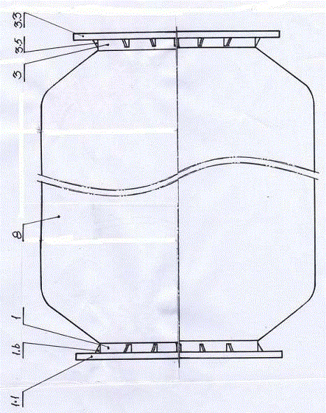
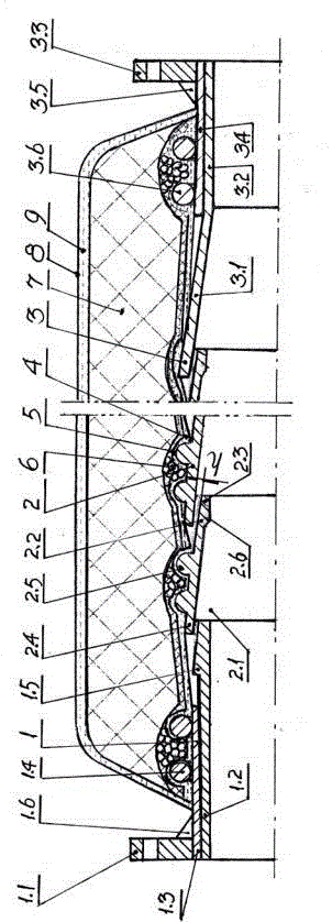
[0030] The design method of a kind of self-floating armored mud discharge pipe of the embodiment 1 of the present invention comprises the overall design of the floating body layer on the mud discharge pipe and the mud discharge pipe and the specific design of each component, and is characterized in that described self-floating The design method of the floating armored pipe body is to meet the technical requirements of the armored mud discharge pipe with a curvature ≥ 35°. The mud discharge pipe is composed of an inlet end pipe, an armored pipe body and an outlet end pipe. The inlet end connection pipe is a casing with inner and outer pipes combined, and a flange is provided at the inlet end, and two ring-shaped positioning fastening rings are arranged on the outside, and the outlet end is inserted into the inlet of the armored pipe body. The inner chamber of the end; the armored pipe body is connected by a plurality of conical pipes, the tapered pipe is an inverted tapered stru...

Embodiment 2

[0049]A design method of an armored mud discharge pipe according to Embodiment 2 of the present invention, a design method of a self-floating armored mud discharge pipe, including the overall design of the mud discharge pipe and the floating body layer on the mud discharge pipe and the components The specific design, the design method of the self-floating armored pipe body described in Embodiment 2 of the present invention is to meet the technical requirements of the bending degree of the armored mud discharge pipe ≥ 35 °, and the described mud discharge pipe is made of It is composed of an inlet end pipe, an armored pipe body and an outlet end pipe. The inlet end pipe is a casing in which the inner and outer pipes are combined and a flange is provided at the inlet end, and two ring-shaped positioning The fastening ring, the outlet end is inserted in the inner cavity of the inlet end of the armored pipe body; the armored pipe body is connected by a plurality of tapered pipes, t...

Embodiment 3

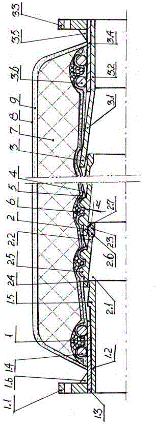
[0068] A design method of a self-floating armored mud discharge pipe according to Embodiment 3 of the present invention, including the overall design of the mud discharge pipe and the floating body layer on the mud discharge pipe and the specific design of each component, the self-floating type The design method of the armored pipe body is to meet the technical requirements of the armored mud discharge pipe with a curvature ≥ 35°. The mud discharge pipe is composed of an inlet end pipe, an armored pipe body and an outlet end pipe. The inlet end connection pipe is a casing with inner and outer pipes combined, and a flange is provided at the inlet end, and two annular positioning fastening rings are arranged on the outside, and the outlet end is inserted into the inlet end of the armored pipe body. Cavity; the armored pipe body is connected by a plurality of conical pipes, the tapered pipe is an inverted tapered structure, and its inlet end shrinks inward along the centerline of ...


PUM


Abstract

The invention discloses a mud pipe and a design method for the self-floating armored mud pipe, and belongs to the technical field of dredging engineering equipment. The design method for the self-floating armored mud pipe comprises overall design of the mud pipe and a floating body layer on the mud pipe and specific design of all parts; and the mud pipe is composed of an inlet end connecting pipe, an armored pipe body and an outlet end connecting pipe. The outer lateral face of the mud pipe is wrapped with a cord fabric powerful elastic material layer, an elastic material layer and a steel wire fastening layer which are bonded with the outer lateral face of the mud pipe; and the floating body layer is characterized in that a light body layer and a protection layer which are integrally connected with the elastic material layer of the mud pipe and are sequentially arranged on the outer side of the elastic material layer of the mud pipe. Compared with the prior art, the design method has the outstanding substantive features and prominent beneficial effects that the technical scheme is reliable, the bending requirement for adjusting the direction of the mud pipe is met, and the wear-resisting property of the mud pipe can be close to that of a metal composite mud pipe.

Description

technical field [0001] The invention relates to the technical field of auxiliary equipment used in dredging engineering, in particular to a design method for a self-floating armored mud discharge pipe used in dredging engineering and the technical field of the mud discharge pipe. Background technique [0002] Mechanical dredging projects such as river courses, waterways, harbor basin dredging, harbor shoals, and wharf foundation trenches all require a large number of mud discharge pipelines connected by mud discharge pipes to achieve transportation, and the indispensable part of the entire mud discharge pipeline is used to adjust The mud discharge elbow in the direction of the mud discharge pipeline, most of the self-floating mud discharge rubber pipes that have been used so far, because the self-floating mud discharge rubber pipe is very fast when transporting solid materials with sharp edges such as rocks, coral reefs, ores, etc. It will be worn out and lose its use value,...

Claims


Application Information

Patent Timeline
Patent Type & Authority Applications(China)
IPC IPC(8): F16L11/08F16L11/133E02F7/10
CPCE02F7/10F16L11/08F16L11/133
Inventor 姜考成唐永胜陈宏礼姜作亮
Owner 姜考成
Why Eureka
Try Eureka