Supercharge Your Innovation With Domain-Expert AI Agents!

Image digitization method using rotary TIN multilevel encrypted network

An encryption network, RG-TIN technology, applied in the direction of image data processing, image coding, instruments, etc., to achieve the effect of simple algorithm, convenient program control, and convenient network construction

Inactive Publication Date: 2015-12-09
黄桂芝
View PDF1 Cites 0 Cited by
  • Summary
  • Abstract
  • Description
  • Claims
  • Application Information

AI Technical Summary

Problems solved by technology

[0003] The purpose of the present invention is to provide a kind of image digitization method that adopts rotating TIN multi-stage encryption network, to solve the interlacing dispersion and echo coordination between triangles in the rotating TIN network of the polygonal image digitization method that adopts rotating TIN network Although it is somewhat different than other layouts improved, but still insufficient compared with the actual needs of a higher level, and when the sampling unit is divided, it is only considered under the condition of two-point control on the side of the triangle, not under the condition of three-point control within the triangle.

Method used


Image

  • Image digitization method using rotary TIN multilevel encrypted network
  • Image digitization method using rotary TIN multilevel encrypted network
  • Image digitization method using rotary TIN multilevel encrypted network

Examples


specific Embodiment approach 1

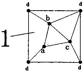
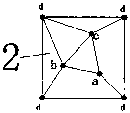
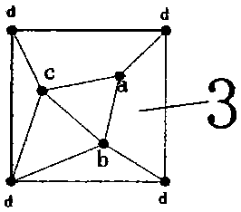
[0015] Specific implementation mode one: the following combination Figure 1 to Figure 9 This embodiment will be described. This embodiment comprises the following steps: 1. Taking 60mm as the side length L of the basic square; 2. Arranging a control point at each of the four vertices of the basic square, and distributing three control points in the basic square. The plane coordinates are (0, 0), (L, 0), (L, L) and (0, L), point a is (0.3L, 0.3L), point b is (0.75L, 0.4L), The point c is (0.4L, 0.8L), connect the three points a, b, c to form a triangle, connect the three points a, b, c to the nearest basic square vertex respectively, and connect the remaining basic square vertex to the basic The two triangle vertices close to it in the square are connected to form the basic unit 1 ( figure 1 ); 3. Rotate the basic unit 1 counterclockwise by 90 degrees to form a primary unit body 2 ( figure 2 ), rotate the basic unit 1 counterclockwise 180 degrees to form the secondary unit...

specific Embodiment approach 2

[0016] Embodiment 2: The difference between this embodiment and Embodiment 1 is that Step A is also included between Step 4 and Step 5 of Embodiment 1, scaling the length or width of the supporting unit to make it a rectangle, and the inside The positions of all control points are adjusted according to the scale. Other steps are still the same as those in Embodiment 1.


PUM


Abstract

The invention relates to an image digitization method. The defects of a polygonal image digitization method adopting a rotary TIN network, for example, staggered dispersion between triangles in the rotary TIN network is still insufficient compared with higher-level needs, and consideration is only taken into the condition that two points on the edge of a triangle are controlled during sampling unit division, are solved. The image digitization method of the invention is mainly characterized by comprising the following steps: an encrypted point is arranged at the center of gravity or inner center of each triangle of an initial rotary TIN network, each encrypted point is connected with the three vertices of the triangle where the encrypted point is located, and the adjacent encrypted points are connected, thus forming a first-level encrypted network of the initial rotary TIN network; encryption is carried out infinitely based on the approach to form n levels of encrypted networks of the initial rotary TIN network; one of the n levels of encrypted networks of the rotary TIN network is selected as a sampling network; and the center of gravity or inner center of each triangle of the sampling network is encrypted again and connection is carried out to form a new encrypted network, the triangles in the new encrypted network are used as sampling units, and the brightness value of a control point in each sampling unit is used as the brightness value of the sampling unit.

Description

technical field [0001] The invention relates to an image digitization method in the field of image digital processing. Background technique [0002] The national invention patent ZL201110110155.7 adopts the polygonal image digitization method of the rotating TIN network. Although the staggered dispersion and echo coordination between the triangles in the rotating TIN network are improved compared with other layouts, it is still insufficient compared with the higher level of actual needs. , and when the sampling unit is divided, it is only considered under the condition of two-point control on the side of the triangle, and there is no defect that it is considered under the condition of three-point control within the triangle. Contents of the invention [0003] The purpose of the present invention is to provide a kind of image digitization method that adopts rotating TIN multi-stage encryption network, to solve the interlacing dispersion and echo coordination between triangl...

Claims


Application Information

Patent Timeline
IPC IPC(8): G06T9/00
Inventor 黄桂芝
Owner 黄桂芝
Features
  • R&D
  • Intellectual Property
  • Life Sciences
  • Materials
  • Tech Scout
  • Unparalleled Data Quality
  • Higher Quality Content
  • 60% Fewer Hallucinations
Learn More