Split stator core and manufacturing method thereof

A stator core, block-type technology, applied in the manufacture of stator/rotor body, magnetic circuit shape/style/structure, magnetic circuit static parts, etc., can solve the problem of high utilization rate of punching materials, blocking magnetic field lines, The problem of low utilization rate of circular iron core punching material, etc., achieves the effect of high utilization rate of material and improvement of magnetic permeability

Inactive Publication Date: 2015-12-09
JINZHOU HALLA ELECTRICAL EQUIP
View PDF9 Cites 0 Cited by
  • Summary
  • Abstract
  • Description
  • Claims
  • Application Information

AI Technical Summary

Problems solved by technology

[0002] Most of the traditional motor stator cores are made of integral circular punching materials, but the stator core with this structure has the problem of low utilization rate of circular core punching materials, which wastes core punching raw materials
[0003] The iron core manufacturing method disclosed by CN1178410, the iron core and the iron core device disclosed by CN1391330 all solve the above-mentioned problems of the traditional motor stator iron core. It forms a plurality of individual iron core segments by overlapping several iron core splicing pieces, and then directly The copper wire is wound on a separate core segment, and then the core segments are connected to form the overall structure of the stator core. The punching material has a high utilization rate and does not waste the core punching raw material, but both have the following defects: adjacent The yokes of the core segments are spliced ​​together to form a whole stator core, that is, the individual core segments have individual teeth, and the yokes are provided with a splicing structure
When this type of spliced ​​stator core structure is applied to single-phase brushless DC motors with concentrated windings, since the spliced ​​seam is located at the yoke where the magnetic flux passes concentratedly, the existence of the seam will block the magnetic flux, seriously affect motor performance

Method used


Image

  • Split stator core and manufacturing method thereof
  • Split stator core and manufacturing method thereof
  • Split stator core and manufacturing method thereof

Examples


Embodiment 1

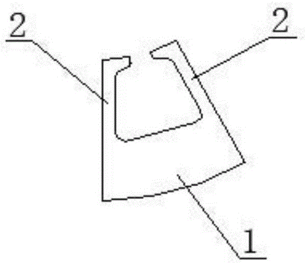
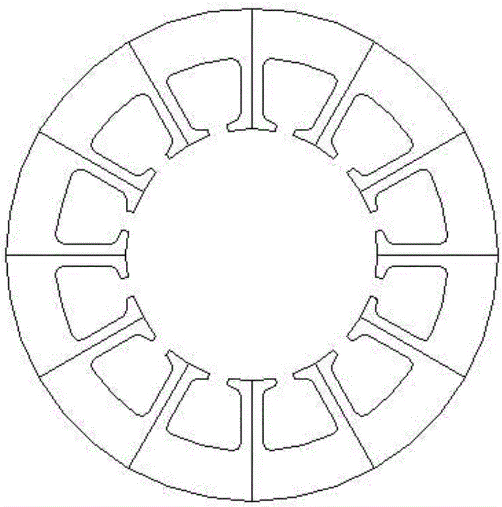
[0017] Such as figure 1 , figure 2 As shown, the block-type stator core includes a plurality of core units assembled into an annular core, which is characterized in that: the core unit consists of a core yoke 1 and two symmetrically arranged at both ends of the core yoke 1 with the same size The half-teeth 2 of two adjacent core units are in contact with each other to form a complete core tooth. Its manufacturing method includes the following steps: 1), punching and forming, using a punching die to punch out the entire sheet of stator core punching material into a plurality of mutually independent stator core punching units, and the stator core punching unit is composed of The sheet core yoke and two sheet half teeth of the same size symmetrically distributed at both ends of the sheet core yoke; Riveting to the required thickness of the stator core, so that the stamping units of the stator core overlap each other to form a core unit, the yoke of the core unit is formed afte...

Embodiment 2

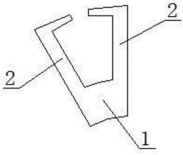
[0019] Such as image 3 , Figure 4 As shown, the block-type stator core is an inner stator core, and the others are the same as in Embodiment 1.


PUM


Abstract

The invention relates to a split stator core and a manufacturing method thereof. The split stator core is composed of a plurality of iron core units which are spliced into a circular ring core; the split stator core is characterized in that each iron core unit is composed of an iron core yoke part and two half-tooth parts; two half-tooth parts are symmetrically arranged at two ends of each iron core yoke part; and the end surfaces of the half-tooth parts of the adjacent two iron core units contact with one another to form an intact iron core tooth part. According to the split stator core, the structural design is relatively reasonable; the motor performance is significantly improved; and raw materials of iron core stamping sheets are reduced, or even a large-volume iron core can also be spliced by small iron core sheets of leftover bits and pieces.

Description

technical field [0001] The invention relates to a motor stator, in particular to a block-type stator core suitable for the winding mode of a concentrated winding single-phase brushless direct-current motor and a manufacturing method thereof. Background technique [0002] Most of the iron cores of traditional motor stators are made of stacked and riveted circular punching materials. However, the stator core with this structure has the problem of low utilization rate of circular core punching materials, which wastes core punching raw materials. . [0003] The iron core manufacturing method disclosed by CN1178410, the iron core and the iron core device disclosed by CN1391330 all solve the above-mentioned problems of the traditional motor stator iron core. It forms a plurality of individual iron core segments by overlapping several iron core splicing pieces, and then directly The copper wire is wound on a separate core segment, and then the core segments are connected to form t...

Claims


Application Information

Patent Timeline
Patent Type & Authority Applications(China)
IPC IPC(8): H02K1/14H02K15/02
Inventor 陈鹏李文奎白昆
Owner JINZHOU HALLA ELECTRICAL EQUIP
Why Eureka
Try Eureka