A method and device for determining mcs level

A level, base station equipment technology, applied in the direction of transmission modification based on link quality, channel coding adjustment, and error detection/prevention using signal quality detectors. low level problem

Active Publication Date: 2018-12-04
DATANG MOBILE COMM EQUIP CO LTD
View PDF5 Cites 0 Cited by
  • Summary
  • Abstract
  • Description
  • Claims
  • Application Information

AI Technical Summary

Problems solved by technology

[0005] There is no limit to the number of PRBs scheduled for PUSCH, and the reception performance of PUSCH at the cell edge cannot be guaranteed
When the user is at the edge of the cell, the path loss is large, and the uplink transmission power is limited, the scheduling MCS level will be adjusted to 0, but the number of PUSCH scheduling PRBs for edge users is not limited. If 96 PRBs are scheduled at this time, the receiving power of a single PRB of the base station equipment will be very high. Low, even if MCS level 0 is scheduled, it cannot be decoded correctly

Method used


Image

  • A method and device for determining mcs level
  • A method and device for determining mcs level
  • A method and device for determining mcs level

Examples


Embodiment 1

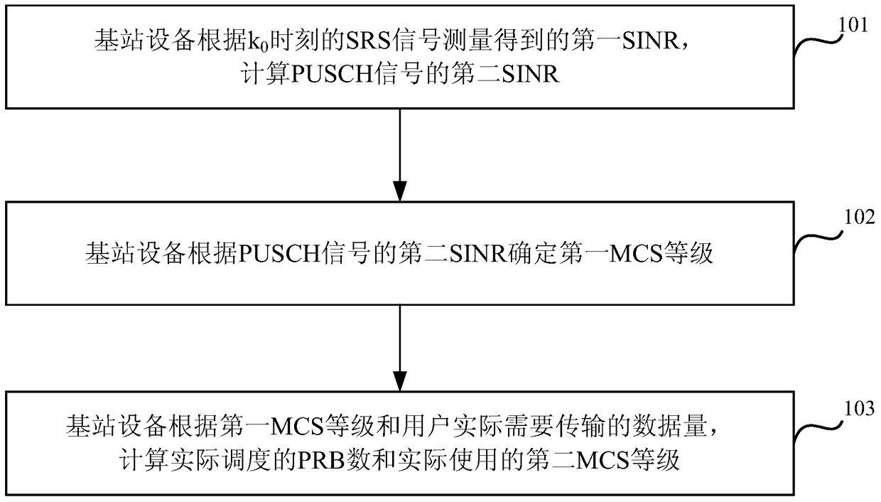
[0058] Aiming at the problems existing in the prior art, Embodiment 1 of the present invention provides a method for determining an MCS level, so as to propose a method for accurately estimating the uplink scheduling MCS and the corresponding number of PRBs. Before describing the specific technical solutions of the embodiments of the present invention, the following related parameters may be defined. PRB_MAX: The maximum number of PRBs that can be scheduled by the base station equipment. The recommended value is 96. PH(i): PHR (Power Headroom Reporting, power headroom reporting) reported by the terminal device at time i. m PUSCH (i): The number of PRBs of the PUSCH of the PHR information of the terminal equipment carried at time i. m SRS : the bandwidth of the SRS (that is, the number of PRBs). P SRS_OFFSET : The power offset of the SRS, which is a configuration parameter. PRB_MAX_noLimt: The transmit power of the terminal device is P CMAX (maximum transmit power) the n...

Embodiment 2

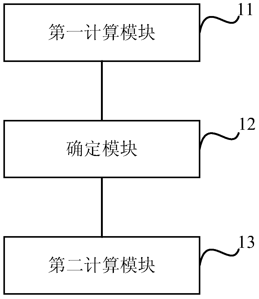
[0085] Based on the same inventive concept as the above method, an embodiment of the present invention also provides a base station device, such as figure 2 As shown, the base station equipment specifically includes:

[0086] The first calculation module 11 is used for k 0 The first signal-to-interference-plus-noise ratio SINR measured by the SRS signal at the moment, and calculate the second SINR of the physical uplink shared channel PUSCH signal;

[0087] A determining module 12, configured to determine the MCS level of the first modulation and coding scheme according to the second SINR;

[0088] The second calculation module 13 is configured to calculate the number of PRBs actually scheduled and the second MCS level actually used according to the first MCS level and the amount of data that the user actually needs to transmit.

[0089] The first calculation module 11 is specifically configured to calculate the second SINR of the PUSCH signal according to the first SINR, t...


PUM


Abstract

The invention discloses a method and equipment for determining an MCS level. The method includes: calculating the second SINR of the PUSCH signal according to the first SINR measured by the SRS signal at time k0 by the base station equipment; determining the second SINR of the PUSCH signal by the base station equipment according to the second SINR The first MCS level: the base station equipment calculates the number of actually scheduled PRBs and the actually used second MCS level according to the first MCS level and the amount of data that the user actually needs to transmit. In the embodiment of the present invention, the MCS level corresponding to the PUSCH scheduling a certain number of PRBs is accurately calculated, so that the MCS level of the PUSCH matches the actual SINR of the PUSCH channel, effectively ensuring the receiving performance of the PUSCH, thereby improving the uplink transmission of the LTE system Efficiency, especially helps to improve the uplink transmission efficiency of cell edge users, ensures the PUSCH transmission performance of cell edge users with large path loss, and helps improve the uplink service rate of edge users.

Description

technical field [0001] The present invention relates to the field of communication technology, in particular to a method and equipment for determining an MCS level. Background technique [0002] In the LTE (Long Term Evolution, long-term evolution) system, the uplink adaptive technology is: the base station equipment estimates the user's uplink PUSCH (Physical Uplink Shared Channel, physical uplink) according to the user's uplink SRS (Sounding Reference Signal, Sounding Reference Signal) signal quality Shared channel) channel quality, and then when scheduling PUSCH, select an MCS (Modulation and Coding Style, modulation and coding style) that matches the user channel quality. Specifically, the base station equipment estimates the user's uplink channel quality SINR (Signal to Interference plus Noise Ratio, signal to interference plus noise ratio) according to the user's uplink SRS signal, and approximately considers that the SINR obtained by the SRS measurement will be equal ...

Claims


Application Information

Patent Timeline
Patent Type & Authority Patents(China)
IPC IPC(8): H04W72/08H04W72/12
CPCH04W72/12H04L1/0005H04L1/0011H04L1/20H04L5/0064H04L5/0046H04L5/0051H04L27/0012H04L27/2602H04B7/0857H04L5/0044
Inventor 孔健汪玲苏进喜
Owner DATANG MOBILE COMM EQUIP CO LTD
Why Eureka
Try Eureka