Swinging hydrofoil tip excitation wave energy conversion device

A conversion device and swing type technology, applied in the directions of hydroelectric power generation, ocean energy power generation, engine components, etc., can solve the problems of low energy conversion efficiency, expensive equipment and complex structure, etc., to ensure the effectiveness, stable and reliable swing structure. Effect

Active Publication Date: 2017-06-13
HARBIN INST OF TECH
View PDF1 Cites 0 Cited by
  • Summary
  • Abstract
  • Description
  • Claims
  • Application Information

AI Technical Summary

Problems solved by technology

[0005] The present invention solves the problems of complex structure, expensive equipment and devices, high power generation cost, low energy conversion efficiency and low power generation voltage in the existing wave energy power generation device, and further provides a swing type hydrofoil end excitation wave energy conversion device

Method used


Image

  • Swinging hydrofoil tip excitation wave energy conversion device
  • Swinging hydrofoil tip excitation wave energy conversion device
  • Swinging hydrofoil tip excitation wave energy conversion device

Examples


specific Embodiment approach 1

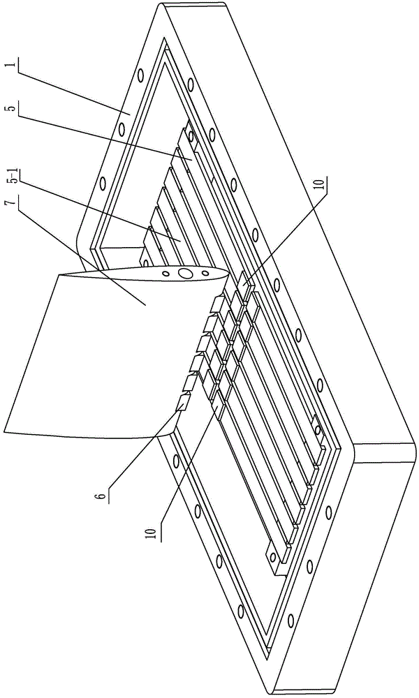
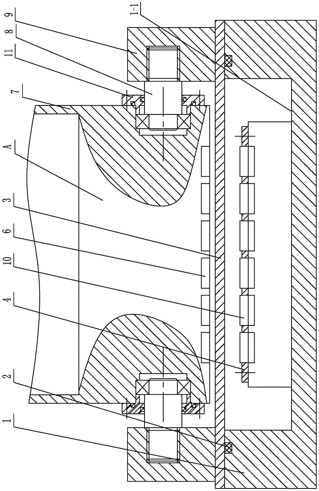
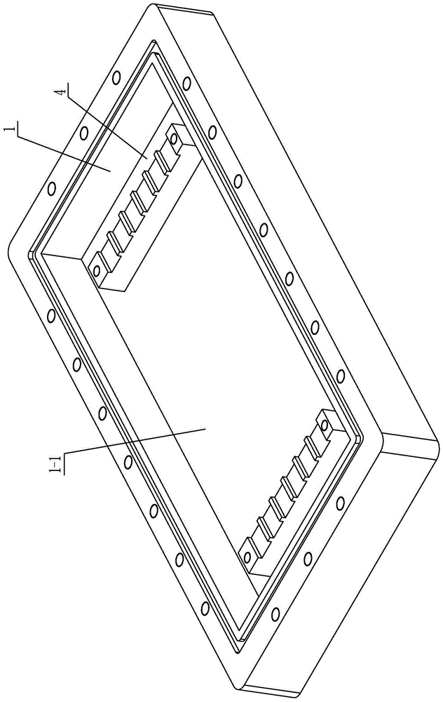
[0010] Specific implementation mode one: combine Figure 1 to Figure 7 Explain that the swing type hydrofoil end excitation wave energy conversion device of this embodiment includes a fixed base 1, a water baffle 3, a swing wing 7, two support bases 9, and two sets of cantilever beam piezoelectric buoyancy devices 5 , a plurality of excitation permanent magnets 6 and a plurality of vibration permanent magnets 10; each group of cantilever beam piezoelectric buoyancy devices 5 includes a plurality of cantilever beam piezoelectric buoyancy devices 5; the magnetic poles of the excitation permanent magnets 6 and the vibration permanent magnets 10 The same property; the fixed base 1 is a fixed base with a groove 1-1, two support bases 9 are fixed side by side on the fixed base 1, the swing wing plate 7 is arranged between the two support bases 9 and the swing wing The two ends of the rear edge of the plate 7 are rotatably connected to the two support seats 9, the water baffle 3 and ...

specific Embodiment approach 2

[0012] Specific implementation mode two: combination Figure 1-Figure 2 Note that the piezoelectric sheet 5-1 of each cantilever piezoelectric buoyant energy device 5 in this embodiment is a piezoelectric ceramic sheet or a polyvinylidene fluoride sheet. When the swing type hydrofoil end excitation wave energy conversion device of the present embodiment is manufactured, the piezoelectric sheet 5-1 is made of piezoelectric ceramics or piezoelectric polymer (polyvinylidene fluoride sheet); Ceramics have strong piezoelectricity, high dielectric constant, and can be processed into any shape; polyvinylidene fluoride has the advantages of flexibility, low density, low impedance and high voltage constant, which can meet actual needs. Others are the same as in the first embodiment.

specific Embodiment approach 3

[0013] Specific implementation mode three: combination Figure 1-Figure 2 It is explained that the piezoelectric sheet 5-1 of each cantilever piezoelectric buoyant energy device 5 in this embodiment is in the shape of a long rectangular sheet. With such arrangement, the processing and manufacturing are convenient, and the practical application is convenient. Others are the same as in the first or second embodiment.


PUM


Abstract

The invention relates to an energy conversion device, in particular to an oscillating type hydrofoil end vibration excitation wave energy conversion device. The problems that an existing wave energy power generation device is complex in structure and high in device manufacturing cost, high in power generation cost and low in energy conversion efficiency and power generation voltage are solved. The oscillating type hydrofoil end vibration excitation wave energy conversion device comprises a fixed base, a water isolation plate, an oscillating wing plate, two supporting bases, two sets of cantilever beam piezoelectric energy floaters, a plurality of vibration excitation permanent magnets and a plurality of vibration receiving permanent magnets. Each set of cantilever beam piezoelectric energy floaters includes a plurality of cantilever beam piezoelectric energy floaters. The fixed base is provided with grooves. The two supporting bases are fixedly installed on the fixed base in parallel. The water isolation plate is placed below the oscillating wing plate and covers the grooves. The water isolation plate is in sealed connection with the fixed base. The two sets of cantilever beam piezoelectric energy floaters and the multiple vibration receiving permanent magnets are arranged inside the grooves. The cantilever beam ends of the multiple cantilever beam piezoelectric energy floaters are fixedly connected with the fixed base. The oscillating type hydrofoil end vibration excitation wave energy conversion device is used for energy conversion and power generation.

Description

technical field [0001] The invention relates to an energy conversion device, in particular to a swing type hydrofoil end excitation wave energy conversion device, which belongs to the field of new energy for ocean wave power generation. Background technique [0002] In recent years, with the increasingly serious energy crisis, new energy technologies have received widespread attention. On some remote islands or offshore operating platforms far from the coastline, energy is scarce and material transportation costs are high, resulting in some equipment not working properly, which brings great inconvenience to the life of island residents and platform staff. The ocean is a very huge energy treasure house. It is estimated that the energy contained in sea waves is as high as 5000GW. If it can be effectively used, it will not only solve the energy problem of people at sea, but also greatly help to alleviate the global energy crisis. Ocean energy reserves are abundant. How to col...

Claims


Application Information

Patent Timeline
Patent Type & Authority Patents(China)
IPC IPC(8): F03B13/14F03B17/06H02N2/18
CPCY02E10/20Y02E10/30Y02P70/50
Inventor 董帝渤陈维山郝亚强石胜君刘军考侯珍秀
Owner HARBIN INST OF TECH
Why Eureka
Try Eureka