Novel load retaining valve structure for excavator
A load-holding valve and excavator technology, which is applied to multi-port valves, valve devices, mechanical equipment, etc., can solve the hidden safety hazards of workers, large leakage in the load-holding valve, and large settlement of excavator sticks and booms. and other problems to achieve the effect of improving stability and security and ensuring rapid response.
- Summary
- Abstract
- Description
- Claims
- Application Information
AI Technical Summary
Problems solved by technology
Method used
Image

Examples
Embodiment 1
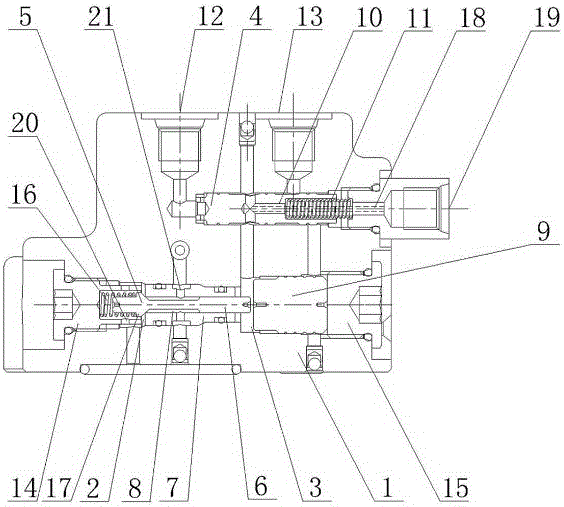
[0021] Such as figure 1 As shown, the present invention provides a new type of load holding valve structure for excavators, including a valve body 1 and an abdominal cavity arranged in the valve body 1. The abdominal cavity includes a first abdominal cavity 2 and a second abdominal cavity located on the right side of the first abdominal cavity 2. Abdominal cavity 3, the first abdominal cavity 2 communicates with the second abdominal cavity 3.
[0022] Such as figure 1 As shown, a cone valve core 5 and a valve sleeve 7 are sequentially arranged in the first abdominal cavity 2 from left to right. The right end of the cone spool 5 is horizontally provided with a push post 6, and the cone spool 5 is movable and located in the first abdominal cavity 2; a through cavity 8 is opened on the horizontal center axis of the valve sleeve 7, and the push post 6 runs through the cavity 8 And its length is longer than the length of the cavity 8.
[0023] The first overflow hole 20 is provi...
Embodiment 2
[0030] The present invention provides a new type of load holding valve structure for excavators, the structure is as described in Embodiment 1, the difference is that: figure 1 As shown, the valve body 1 is also provided with a first screw plug 14, which is located on the left side of the first abdominal cavity 2; the right end of the first screw plug 14 is provided with a damping spring 16, and the cone valve core 5 A boss 17 is provided, the left end of the cone valve core 5 passes through the damping spring 16 and is located in the first screw plug 14 , and the damping spring 16 is located between the boss 17 and the first screw plug 14 . When the plunger 9 pushes the cone valve core 5 to move to the left, the boss 17 compresses the damping spring 16 and at the same time the cone seal structure formed by the cone valve core 5 and the valve sleeve 7 is opened, at this time the high-pressure oil in the first abdominal cavity enters the valve sleeve 7 through cavity 8, and the...
Embodiment 3
[0032] The present invention provides a new cone sealing structure, the structure is as described in Embodiment 1, the difference is that: figure 1As shown, there is a discharge hole 18 on the central axis of the pilot valve core 10 ; the valve body 1 is also provided with an oil discharge port 19 , and the oil discharge port 19 communicates with the second abdominal cavity 3 through the overflow hole 18 . The discharge hole 18 can remove excess hydraulic oil accumulated and stored in the second abdominal cavity 3 to ensure the smooth movement of the plunger 9 .
[0033] The working principle of the present invention is as follows:
[0034] (1) When a load such as a boom is held, the first abdominal cavity 2 is a high-pressure chamber, and the hydraulic oil presses the cone valve core 5 onto the valve sleeve 7; this structure can control the leakage in the load holding valve to 2ml within / min.
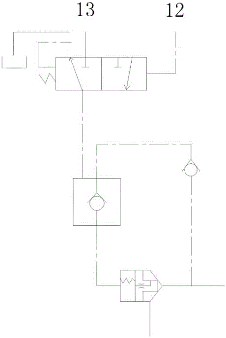
[0035] (2) The P1 oil inlet 12 is fed with pilot oil to push the pilot spool 10...
PUM
 Abstract
Description
Claims
Application Information
 - R&D
- Intellectual Property
- Life Sciences
- Materials
- Tech Scout
- Unparalleled Data Quality
- Higher Quality Content
- 60% Fewer Hallucinations
Browse by: Latest US Patents, China's latest patents, Technical Efficacy Thesaurus, Application Domain, Technology Topic, Popular Technical Reports.
© 2025 PatSnap. All rights reserved.Legal|Privacy policy|Modern Slavery Act Transparency Statement|Sitemap|About US| Contact US: help@patsnap.com