Self-locking snap ring

A self-locking, clasp technology, applied in the direction of connecting components, mechanical equipment, friction-clamped removable fasteners, etc.

Active Publication Date: 2015-12-16
HARBIN DONGAN ENGINE GRP
View PDF8 Cites 3 Cited by
  • Summary
  • Abstract
  • Description
  • Claims
  • Application Information

AI Technical Summary

Problems solved by technology

At the same time, in order to ensure the reliability of installation and the economy of maintenance, the snap ring needs to be able to be quickly installed, locked and disassembled. At present, there is no snap ring with this function at the same time.

Method used


Image

  • Self-locking snap ring
  • Self-locking snap ring

Examples


Embodiment Construction

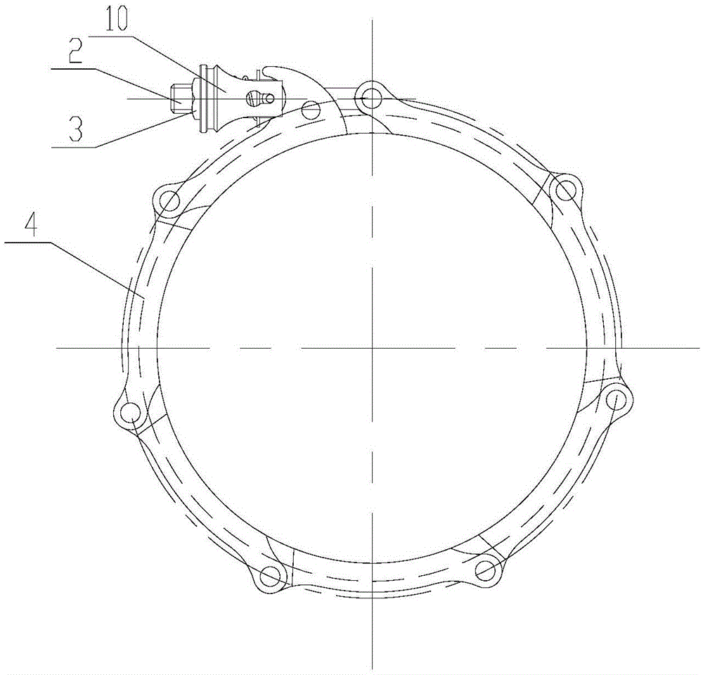
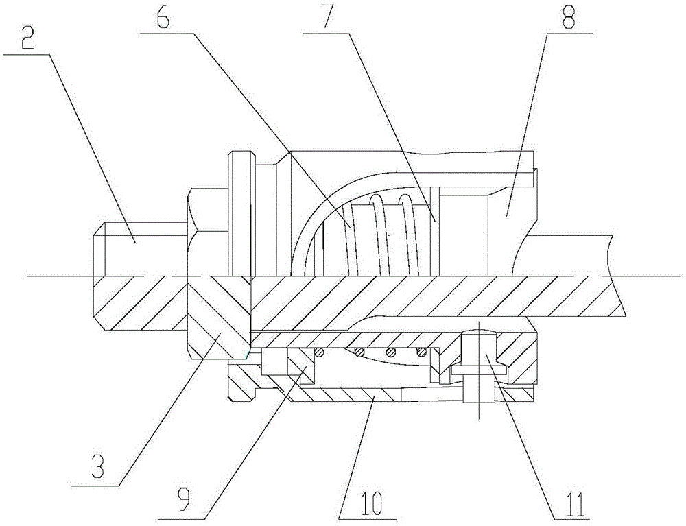
[0008] As shown in the figure, the self-locking snap ring includes a snap ring body and a lock assembly. The snap ring body is composed of several joints 4 spliced ​​together in sequence. The lock assembly includes bolts 2, nuts 3, and springs 6. , screw sleeve 8, lock housing 10, one end of the bolt 2 is hinged on one end of the snap ring body, and the other end passes through the other end of the snap ring body and the screw sleeve 8 to install the nut 3, and the nut 3 passes through the screw sleeve 8 Tighten the clasp body, the lock housing 10 is arranged outside the screw sleeve 8, the spring 6 is respectively pressed on the steps inside the lock housing 10 and the outside of the screw sleeve 8, and the end of the lock housing 10 is positioned under the action of the spring 6. The outside of the nut 3 is matched with the outer contour of the nut 3, the screw sleeve 8 is provided with a pin 11, the bolt 2 is provided with an axial groove, and the lock housing 10 is provided...


PUM


Abstract

The invention relates to a self-locking snap ring which comprises a snap ring body composed of multiple connecting joints hinged together in sequence, and a lock assembly. One end of a bolt of the lock assembly is hinged to one end of the snap ring body. The other end of the bolt penetrates the other end of the snap ring body and a swivel nut and is then provided with a nut. A lock shell is arranged outside the swivel nut. A spring is pressed on the lock shell and the swivel nut. The end of the lock shell is matched with the outer contour of the nut. The swivel nut is provided with a pin. The pin extends into an axial groove of the bolt and an axial through hole of the lock shell respectively. Compared with a traditional quick-detached snap ring, the self-locking snap ring has the beneficial effects that the self-locking and detaching functions are more convenient, the snap ring is rapidly installed, locked and detached, and the requirements for installation reliability and repair economic efficiency of the snap ring are met.

Description

technical field [0001] The patent of the present invention relates to a snap ring, especially a snap ring with self-locking function, which realizes the installation, locking and disassembly of the snap ring itself. Background technique [0002] Snap rings are used in many fields, and they are widely used in the aviation field. When the snap ring is in use, in order to ensure the clamping is firm, the quick-release snap ring is generally locked after the clamping. The locking devices of the more advanced snap rings now have self-locking functions. At the same time, in order to ensure the reliability of installation and the economy of maintenance, the snap ring needs to be able to be quickly installed, locked and disassembled. Currently, there is no snap ring with this function at the same time. Contents of the invention [0003] The purpose of the present invention is to provide a snap ring, which not only has the self-locking function, but also can realize fast installat...

Claims


Application Information

Patent Timeline
Patent Type & Authority Applications(China)
IPC IPC(8): F16B2/20
Inventor 宋剑锋安伯堃武程黄国权胡红艳李悦宫伟辛旭生刘亚琴姚勇吉洪振刘兰涛孟凡吉
Owner HARBIN DONGAN ENGINE GRP
Why Eureka
Try Eureka