

Automatic leveling structure
An automatic leveling and self-adjusting technology, applied in the field of line casting instruments, can solve problems such as inconvenience, uneven placement, and inclination, and achieve the effects of extending service life, improving impact resistance and convenient adjustment.
- Summary
- Abstract
- Description
- Claims
- Application Information
AI Technical Summary
Problems solved by technology
Method used
Image

Examples
Embodiment 2
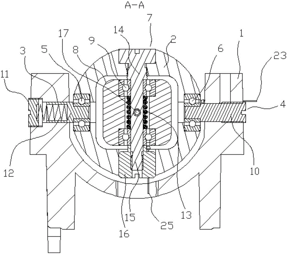
[0024] Embodiment 2: the structure and specific implementation of this embodiment are the same as embodiment 1, and its difference is, as Figure 3 to Figure 6As shown in: the inner compensation shaft is provided with a tube hole, and the tube hole is provided with a sliding positioning tube 17 that is slidingly fitted with the tube hole, and the axis of the sliding positioning tube is perpendicular to the axis of the inner compensation shaft , the sliding positioning tube is slidingly connected with the inner compensation shaft, the inner compensation seat is provided with a positioning hole, the diameter of the positioning hole is adapted to the outer diameter of the sliding positioning tube, and the positioning hole and the sliding positioning tube Coaxial, the inner compensating seat is provided with a lower storage tank 18, the lower storage tank is located below the positioning hole and communicates with the positioning hole, the positioning hole is provided with a top bl...
PUM
 Abstract
Description
Claims
Application Information