Automobile rear cantilever mounting hole distance detection measurement tool
A rear suspension beam and mounting hole technology, which is applied in the field of measuring tools for the installation hole spacing of the rear suspension beam of automobiles, can solve the problems of automobile quality reduction and other problems
- Summary
- Abstract
- Description
- Claims
- Application Information
AI Technical Summary
Problems solved by technology
Method used
Image
Examples
Embodiment 1
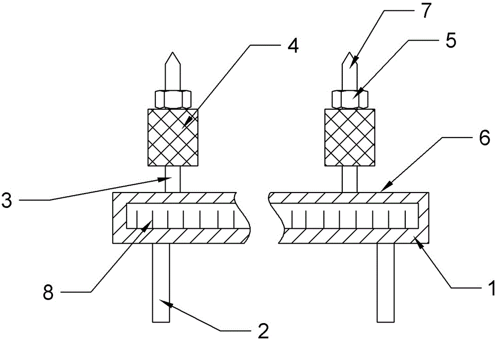
[0016] Example 1, such as figure 1 As shown, the measuring tool for detecting the distance between the mounting holes of the rear suspension beam of the automobile includes a measuring tool body 1, the measuring tool body 1 is in a rectangular shape as a whole, and the length of the measuring tool body 1 is 2000 mm, which is compatible with the length of the rear suspension beam. The lower end of the measuring tool body 1 is fixed with two support frames 2 by bolts, so as to keep the measuring tool body 1 level with the ground and ensure the accuracy of the measuring tool test results. One end of the measuring tool body 1 is fixedly connected with a fixed rod 3. The top of the fixed rod 3 is conical. 5 is threadedly matched with the screw thread of the fixing rod 3, and the fixing rod 3 presses the rubber 4 through the nut 5 to make it interference fit with the mounting hole. The measuring tool body 1 is provided with a chute 6, and the chute 6 is slidably connected with the ...
Embodiment 2
[0017] The difference between Embodiment 2 and Embodiment 1 is that the length of the measuring tool body 1 is 2300 mm.
Embodiment 3
[0018] The difference between Embodiment 3 and Embodiment 1 is that the length of the measuring tool body 1 is 2500 mm.
[0019] First place the rear suspension beam on the horizontal frame, first pass the top of the fixed rod 3 through a hole, rotate the nut 5 downwards, and then deform the rubber 4 to both sides, and the rubber 4 has an interference fit with its mounting hole. Since the rubber 4 is circumferentially arranged around the fixed rod 3, it is located at the center of the circle. Thus, the position of the top of the fixed rod 3 accurately locates the center of the circle of the installation hole. Simultaneously, slide the slide bar 7 to make it interference fit with another installation hole, so as to determine its center of circle. In this way, the distance between the tops of the fixed bar 3 and the slide bar 7 on the reading scale reticle 8 is the distance between the centers of the two mounting holes.
PUM
 Abstract
Description
Claims
Application Information
 - R&D
- Intellectual Property
- Life Sciences
- Materials
- Tech Scout
- Unparalleled Data Quality
- Higher Quality Content
- 60% Fewer Hallucinations
Browse by: Latest US Patents, China's latest patents, Technical Efficacy Thesaurus, Application Domain, Technology Topic, Popular Technical Reports.
© 2025 PatSnap. All rights reserved.Legal|Privacy policy|Modern Slavery Act Transparency Statement|Sitemap|About US| Contact US: help@patsnap.com

