Three-channel microscope interface

A microscope and three-channel technology, applied in the field of optical imaging, can solve the problems of difficult adjustment of image magnification, complex structure, and no microscope interface in the shooting area of ​​three cameras

Inactive Publication Date: 2015-12-16
HUAZHONG UNIV OF SCI & TECH
View PDF5 Cites 3 Cited by
  • Summary
  • Abstract
  • Description
  • Claims
  • Application Information

AI Technical Summary

Problems solved by technology

[0003] But at present, there is no microscope interface to achieve three-channel imaging, especially for scientific research cameras, the size is large, and it is difficult for them to share one imaging tube lens
If we use a relay lens, not only

Method used


Image

  • Three-channel microscope interface
  • Three-channel microscope interface

Examples


Embodiment Construction

[0014] In order to make the object, technical solution and advantages of the present invention clearer, the present invention will be further described in detail below in conjunction with the accompanying drawings and embodiments. It should be understood that the specific embodiments described here are only used to explain the present invention, not to limit the present invention. In addition, the technical features involved in the various embodiments of the present invention described below can be combined with each other as long as they do not constitute a conflict with each other.

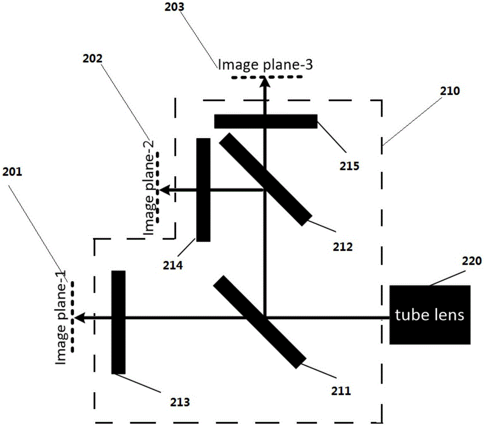
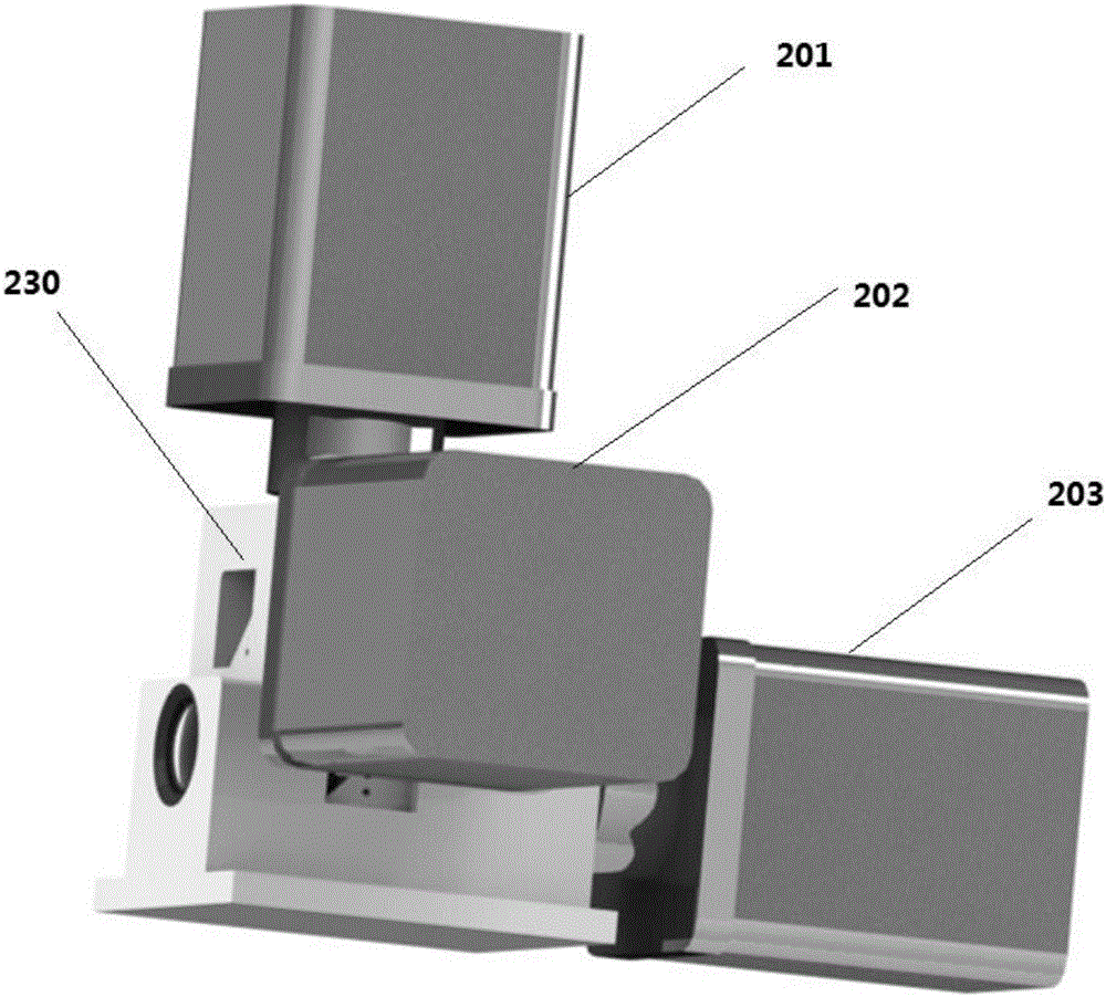
[0015] The three-channel microscope interface provided by the present invention includes a housing 230 , a spectroscopic module 210 and a tube lens 220 .

[0016] There are three light-transmitting holes on the housing, and the housing has the same camera interface outside each light-transmitting hole. Preferably, the light-transmitting hole is equipped with an optical filter corresponding to t...


PUM


Abstract

The invention discloses a three-channel microscope interface which includes a housing, a beam splitting module and a tube lens. Three light holes are disposed in the housing. The light splitting module is disposed in the housing, and includes a first dichroscope and a second dichroscope which are arranged in parallel. Incident mixed light passes through the tube lens and falls onto the first dichroscope to produce first transmitting light and first reflecting light. The first transmitting light emits from the light holes at the corresponding position on the housing. The first reflecting light falls onto the second dichroscope to produce second transmitting light and second reflecting light. The second transmitting light and the second reflecting light emit respectively through the light holes at the corresponding positions on the housing. Optical paths of the incident light from the tube lens to image planes of the light holes are the same. The interface allows three cameras to share one imaging tube lens, the imaging amplification factors of the channels are exactly the same, and when large samples are subjected to scan imaging, no problem will occur in the stitching of the channels and the matching of all the channels.

Description

technical field [0001] The invention belongs to the field of optical imaging, and more specifically relates to a three-channel microscope interface. Background technique [0002] Photomicrography is an integral part of the use of modern microscopes. Due to the continuous development of fluorescence imaging, in the field of multi-spectral color separation imaging that pursues speed, such as the acquisition of multi-color microscopic images of large samples or the acquisition of multi-color microscopic images of a large number of samples, simultaneous three-band imaging is required. [0003] But at present, there is no microscope interface to achieve three-channel imaging, especially for scientific research cameras, which are relatively large in size, making it difficult for them to share one imaging tube lens. If we use a relay lens, not only the structure is complicated, but also the shooting area and image magnification of the three cameras are difficult to adjust, which w...

Claims


Application Information

Patent Timeline
IPC IPC(8): G02B21/36
CPCG02B21/362
Inventor 曾绍群吕晓华尚振华杨涛黄凯
Owner HUAZHONG UNIV OF SCI & TECH
Why Eureka
Try Eureka