Complex optimal control method for reactive power of wind power system in grid voltage sag fault

A grid voltage and wind power system technology, applied in reactive power adjustment/elimination/compensation, flexible AC transmission system, wind power generation, etc., can solve the problem of high cost, failure to meet low voltage ride-through requirements, slow response speed and difficult to meet grid operation Questions such as requirements

Active Publication Date: 2015-12-16
HUNAN UNIV
View PDF4 Cites 10 Cited by
  • Summary
  • Abstract
  • Description
  • Claims
  • Application Information

AI Technical Summary

Problems solved by technology

Traditional control methods use different capacitor banks and static power conversion devices (such as SVC devices, TSC devices, static synchronous compensators), or use the reactive power compensation characteristics of the motor itself (such as doubly-fed induction motors) to achieve reactive power compensation , but the reactive power that the above method can provide is limited, and the cost is high; the use of adding an unloading circuit on the DC side is only suitable for short-term voltage drops and cannot meet the requirements of low voltage when the grid voltage drop is deep and lasts for a long time. Ride-through requirements; adding an additional reactive power compensation control device on the grid side has a slow response speed and is difficult to meet the grid operation requirements during deep drops

Method used


Image

  • Complex optimal control method for reactive power of wind power system in grid voltage sag fault
  • Complex optimal control method for reactive power of wind power system in grid voltage sag fault
  • Complex optimal control method for reactive power of wind power system in grid voltage sag fault

Examples


Embodiment Construction

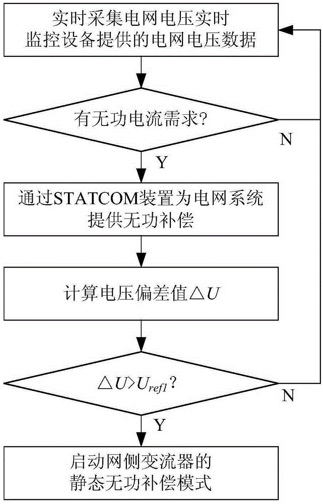
[0051] Such as figure 1 As shown, the steps of the wind power system reactive power comprehensive optimization control method in this embodiment include:

[0052] 1) Real-time collection of grid voltage data provided by grid voltage real-time monitoring equipment;

[0053] 2) According to the grid voltage data, it is judged whether the wind turbine itself has a reactive current demand, if there is a reactive current demand, skip to step 3), otherwise skip to step 1);

[0054] 3) Provide reactive power compensation for the grid system through the static synchronous compensator;

[0055] 4) Change the grid voltage U pcc with a preset reference voltage U pccref The voltage deviation value ΔU between, judge that the voltage deviation value ΔU is greater than the first preset threshold value U ref1 Whether it is true, if true, start the static reactive power compensation mode of the grid-side converter, so that the grid-side converter and the static synchronous compensator prov...


PUM


Abstract

The invention discloses a complex optimal control method for reactive power of a wind power system in a grid voltage sag fault. The method comprises the following steps: reading grid voltage data provided by grid voltage real-time monitoring equipment in real time; judging whether a wind turbine generator has reactive current requirements or not; if so, providing reactive compensation for a grid system through a static synchronous compensator, calculating a voltage deviation value [delta]U between the grid voltage U<pcc> and the preset reference voltage U<pccref>, and judging whether the voltage deviation value [delta]U is greater than a first preset threshold U<ref1> or not; and if so, starting a static reactive compensation mode of a grid-side converter, and enabling the grid-side converter and the static synchronous compensator to synchronously provide reactive compensation to the grid system. According to the complex optimal control method, the voltage of a grid-connected common connection point can be stabilized; and the low-voltage ride through capability of a wind power generation system is enhanced.

Description

technical field [0001] The invention relates to a wind power system reactive power comprehensive optimization technology, in particular to a wind power system reactive power comprehensive optimization control method under grid voltage drop faults. Background technique [0002] When the voltage of the grid-connected point of the wind farm drops, the low-voltage ride-through capability index of the wind farm requires that the wind turbines must provide reactive power support to the grid-connected point to restore its voltage while operating safely without disconnecting from the grid. Traditional control methods use different capacitor banks and static power conversion devices (such as SVC devices, TSC devices, static synchronous compensators), or use the reactive power compensation characteristics of the motor itself (such as doubly-fed induction motors) to achieve reactive power compensation , but the reactive power that the above method can provide is limited, and the cost i...

Claims


Application Information

Patent Timeline
Patent Type & Authority Applications(China)
IPC IPC(8): H02J3/18H02J3/38
CPCY02E10/76Y02E40/10
Inventor 高剑黄守道李慧敏罗德荣王家堡彭婧吕铭晟
Owner HUNAN UNIV
Why Eureka
Try Eureka