Core pulling mechanism for injection mold

A core-pulling mechanism and injection mold technology, applied in the field of injection-mold core-pulling mechanisms, can solve the problems of complexity, low production efficiency, and poor sliding accuracy of large and small sliders.

Active Publication Date: 2015-12-23
NINGBO FANGZHENG TOOL
View PDF3 Cites 5 Cited by
  • Summary
  • Abstract
  • Description
  • Claims
  • Application Information

AI Technical Summary

Problems solved by technology

[0002] At present, due to the complex product structure, there is an injection mold that requires a small slider to slide for a certain distance, and then the small slider and the large slider are pulled out together; in order to realize the delay action during core pulling in the prior art, most of them use The most popular is the combination of oblique rods and waist holes, but this structure makes the opening distance between the upper and lower molds large enough, otherwise the second core-pulling action cannot be realized, which leads to a larger overall mold and requires more space for the mold to be used. It is large enough to limit the scope of use of the mold, and it also makes the entire production cycle longer and the production efficiency lower; some of them use marbles to lock between the large and small sliders, but due to the existence of springs, during use Bite marks and scratches are prone to appear between the middle pin and the lock hole and on the lower end surface of the small slider, which will increase the friction force of the large and small sliders during the sliding process, which will easily lead to heat concentration, thereby deteriorating the sliding accuracy of the large and small sliders. The use stability is poor, and the service life is also shortened

Method used


Image

  • Core pulling mechanism for injection mold
  • Core pulling mechanism for injection mold
  • Core pulling mechanism for injection mold

Examples


Embodiment 1

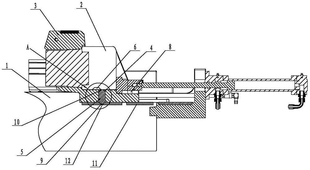
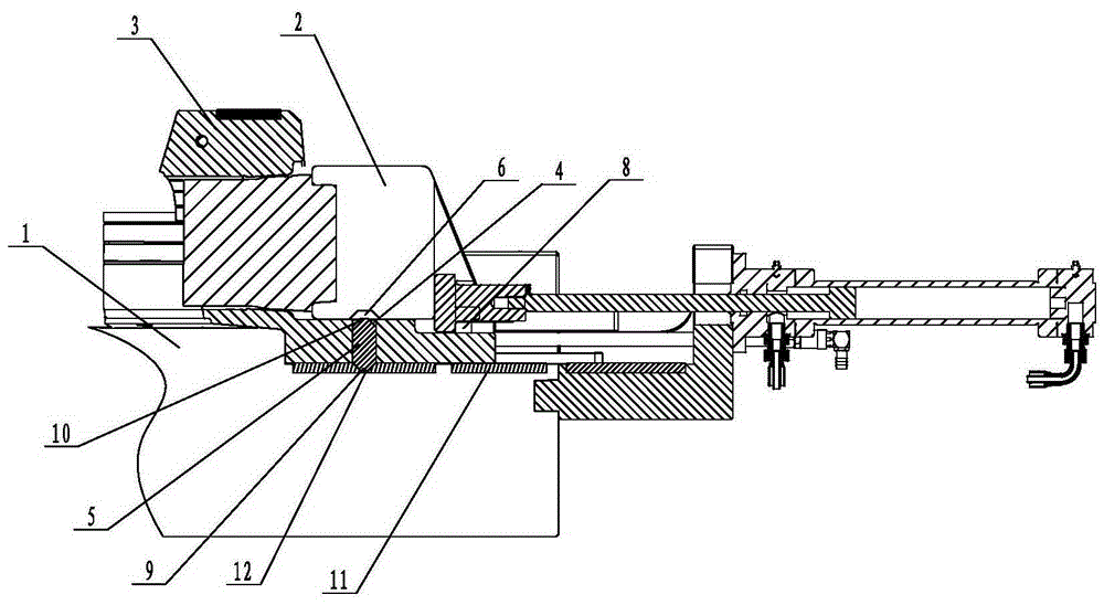
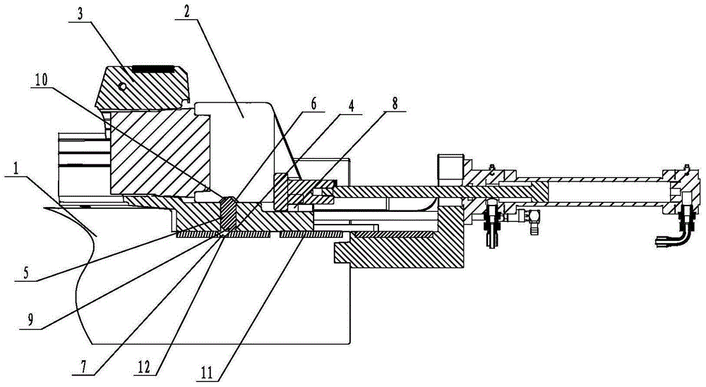
[0021] Such as figure 1 , figure 2 , image 3 , Figure 4 and Figure 5 Shown, a kind of injection mold core-pulling mechanism, it comprises fixed mold 1, small slider 2 and big slider 3 (also includes other parts of course, but because the invention point that does not relate to the invention of the present invention, so no longer here Repeat), the large slider 3 is slidably connected to the fixed mold 1, the small slider 2 is slidably connected to the large slider 3, and the large slider 3 below the small slider 2 is provided with a through hole 4 , the limit block 5 is slidably connected in the through hole 4; the first limit hole 6 that can cooperate with the upper end of the limit block 5 is provided under the small slider 2, generally the first limit hole The depth of 6 is slightly greater than the height of the second protrusion 10, and the upper end surface of the fixed mold 1 is provided with a second limiting hole 7 that can cooperate with the lower end of the l...

Embodiment 2

[0028] The first protrusion 9 is arc-shaped, and the central angle corresponding to the arc is less than 90° (30° in this example, but also 5°, 20°, 45°, 80° or 85°, etc.).

[0029]When the mold is in the mold closing state, the limit block 5 is located in the space formed by the through hole 4 and the second limit hole 7. When the mold is opened and the core is pulled, the small slider 2 moves to the right under the action of the oil cylinder until it is forcibly limited. Positioning block 8 is limited. At this time, the first limiting hole 6 is just above the limiting block 5, and the oil cylinder continues to work. At this time, the small slider 2 and the large sliding block 3 move to the right together, and because the limiting block 5 The top is empty, and under the action of the first protrusion 9 and the second limit hole 7 at the lower end of the stopper 5, the stopper 5 will move on the trapezoidal or arc-shaped first protrusion as the large slider 3 continues to move....


PUM

PropertyMeasurementUnit
angleaaaaaaaaaa

Abstract

A core pulling mechanism for an injection mold comprises a fixed die, a small sliding block and a big sliding block. A through hole is formed in the position, below the small sliding block, of the big sliding block. A limiting block is connected into the through hole in a sliding manner. A first limiting hole capable of being in limiting fit with the upper end of the limiting block is arranged in the lower portion of the small sliding block. A second limiting hole capable of being limiting fit with the lower end of the limiting block is formed in the upper end face of the fixed die. The length of the through hole plus the depth of the second limiting hole equals the length of the limiting block. The interval between the first limiting hole and the second limiting hole equals the sliding distance of the small sliding block relative to the big sliding block. A forcing limiting block for the small sliding block is arranged on the big sliding block. The interval between the forcing limiting block and the small sliding block equals the interval between the first limiting hole and the second limiting hole. The lower end of the limiting block is provided with a trapezoid or arc first protrusion. The second limiting hole is the same as the first protrusion in shape. Compared with the prior art, the core pulling mechanism has the beneficial effects of being small in size, simple in structure, good in use stability and long in service life.

Description

technical field [0001] The invention relates to a core pulling mechanism of an injection mold. Background technique [0002] At present, due to the complex product structure, there is an injection mold that requires a small slider to slide for a certain distance, and then the small slider and the large slider are pulled out together; in order to realize the delay action during core pulling in the prior art, most of them use The most popular is the combination of oblique rods and waist holes, but this structure makes the opening distance between the upper and lower molds large enough, otherwise the second core-pulling action cannot be realized, which leads to a larger overall mold and requires more space for the mold to be used. It is large enough to limit the scope of use of the mold, and it also makes the entire production cycle longer and the production efficiency lower; some of them use marbles to lock between the large and small sliders, but due to the existence of sprin...

Claims


Application Information

Patent Timeline
Patent Type & Authority Applications(China)
IPC IPC(8): B29C45/33B29C45/40
CPCB29C45/33B29C45/40
Inventor 魏小强赖敏煜应可国俞能军
Owner NINGBO FANGZHENG TOOL
Why Eureka
Try Eureka