Injection mold core pulling mechanism
A technology of core-pulling mechanism and injection mold, which is applied in the field of injection mold core-pulling mechanism, and can solve problems such as poor stability in use, inability to realize secondary core-pulling, and poor sliding accuracy of large and small sliders.
- Summary
- Abstract
- Description
- Claims
- Application Information
AI Technical Summary
Problems solved by technology
Method used
Image
Examples
Embodiment 1
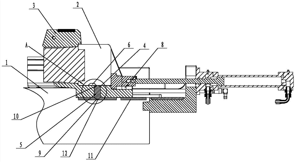
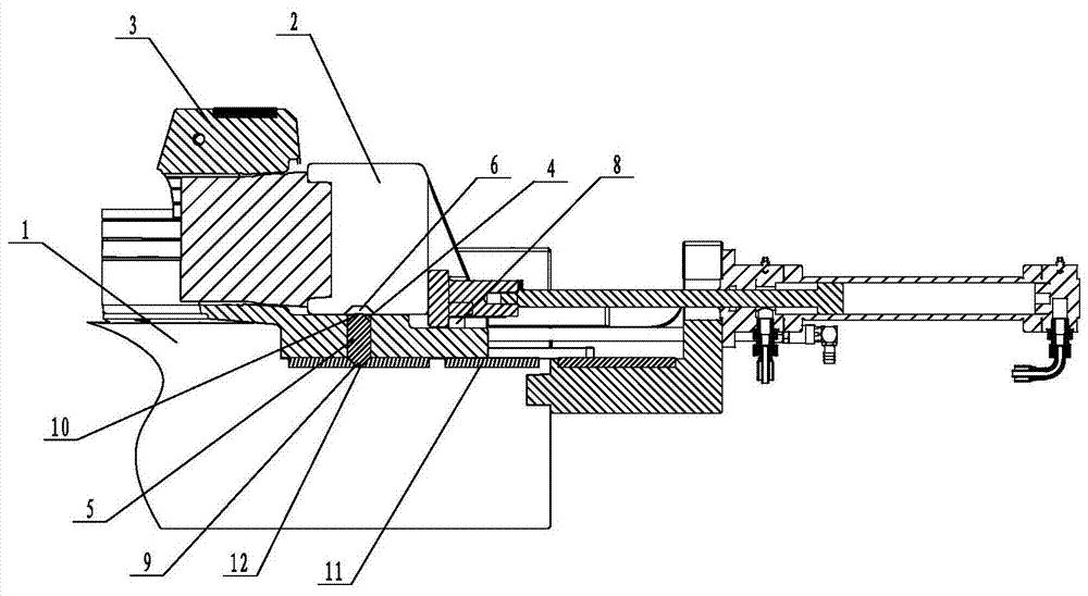
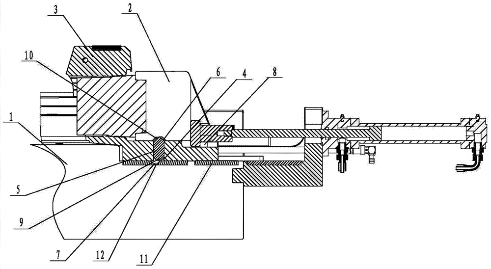
[0021] Such as figure 1 , figure 2 , image 3 , Figure 4 and Figure 5 Shown, a kind of injection mold core-pulling mechanism, it comprises fixed mold 1, small slider 2 and big slider 3 (also includes other parts of course, but because the invention point that does not relate to the invention of the present invention, so no longer here Repeat), the large slider 3 is slidably connected to the fixed mold 1, the small slider 2 is slidably connected to the large slider 3, and the large slider 3 below the small slider 2 is provided with a through hole 4 , the limit block 5 is slidably connected in the through hole 4; the first limit hole 6 that can cooperate with the upper end of the limit block 5 is provided under the small slider 2, generally the first limit hole The depth of 6 is slightly greater than the height of the second protrusion 10, and the upper end surface of the fixed mold 1 is provided with a second limiting hole 7 that can cooperate with the lower end of the l...
Embodiment 2
[0028] The first protrusion 9 is arc-shaped, and the central angle corresponding to the arc is less than 90° (30° in this example, but also 5°, 20°, 45°, 80° or 85°, etc.).
[0029]When the mold is in the mold closing state, the limit block 5 is located in the space formed by the through hole 4 and the second limit hole 7. When the mold is opened and the core is pulled, the small slider 2 moves to the right under the action of the oil cylinder until it is forcibly limited. Positioning block 8 is limited. At this time, the first limiting hole 6 is just above the limiting block 5, and the oil cylinder continues to work. At this time, the small slider 2 and the large sliding block 3 move to the right together, and because the limiting block 5 The top is empty, and under the action of the first protrusion 9 and the second limit hole 7 at the lower end of the stopper 5, the stopper 5 will move on the trapezoidal or arc-shaped first protrusion as the large slider 3 continues to move....
PUM
| Property | Measurement | Unit |
|---|---|---|
| angle | aaaaa | aaaaa |
Abstract
Description
Claims
Application Information
 - R&D
- Intellectual Property
- Life Sciences
- Materials
- Tech Scout
- Unparalleled Data Quality
- Higher Quality Content
- 60% Fewer Hallucinations
Browse by: Latest US Patents, China's latest patents, Technical Efficacy Thesaurus, Application Domain, Technology Topic, Popular Technical Reports.
© 2025 PatSnap. All rights reserved.Legal|Privacy policy|Modern Slavery Act Transparency Statement|Sitemap|About US| Contact US: help@patsnap.com


