
A card automatic laminating machine

A laminator, automatic technology, applied in the direction of lamination, lamination device, lamination auxiliary operation, etc., can solve the problems of limited service life of the conveyor belt, high failure rate and defective rate, work in high temperature environment, etc., to achieve cost Low cost, extended service life, and the effect of improving service life

Inactive Publication Date: 2018-01-02
济宁市通联电器厂
View PDF4 Cites 0 Cited by
  • Summary
  • Abstract
  • Description
  • Claims
  • Application Information

AI Technical Summary

Problems solved by technology

In order to improve production efficiency, those skilled in the art have proposed a laminator equipment that uses a conveyor belt to circulate materials, and the raw materials to be pressed are sent between the press heads through the conveyor belt. The conveyor belt needs to be hot-pressed together with the material, resulting in a very limited service life of the conveyor belt, requiring frequent shutdowns for replacement, and the material often sticks to the conveyor belt after hot-pressing, resulting in a high failure rate and defective product rate
In addition, the current existing laminator equipment uses pneumatic cylinders or hydraulic cylinders to drive hot or cold pressure heads for pressing and bonding to realize hot pressing or cooling of multi-layer materials. The cylinders are all installed above the indenter, and the movable indenter is driven to press the fixed indenter from top to bottom. In order to match the feeding system, the pressing position of the indenter needs to maintain a certain height, so the lamination of the downward press The height of the machine itself is high, and the center of gravity is at the top, so the stability is poor. It is necessary to set a counterweight at the bottom. The high-temperature gas around the hot head always flows upwards, so the pneumatic cylinder or hydraulic cylinder always works in a high-temperature environment, and the service life will be severely affected

Method used


Image

  • A card automatic laminating machine
  • A card automatic laminating machine
  • A card automatic laminating machine

Examples


Embodiment Construction

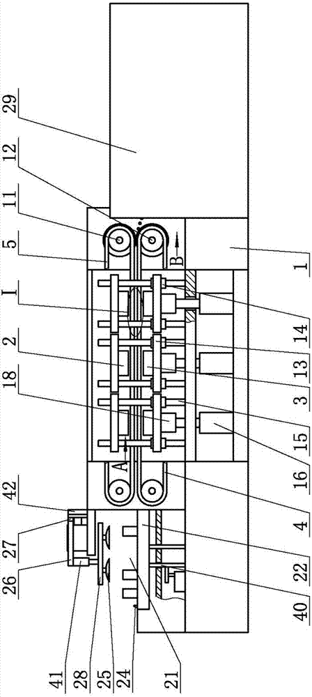
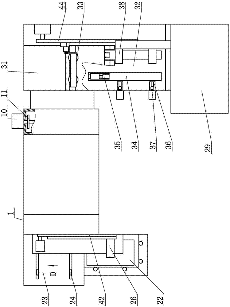
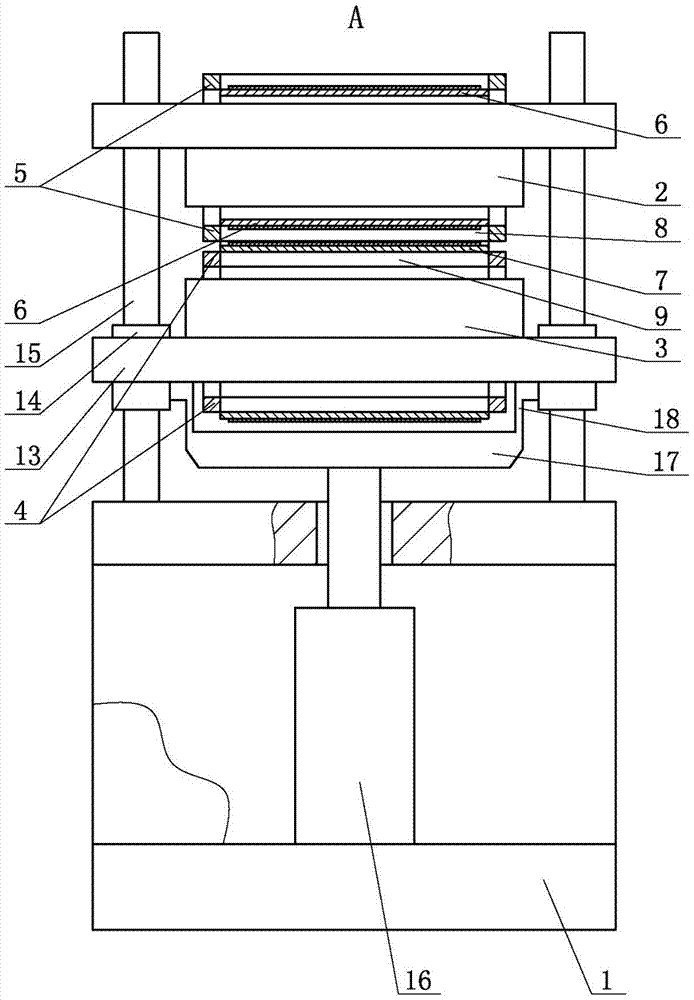
[0014] A card automatic laminating machine according to the present invention includes a frame 1, which is characterized in that: an automatic feeding device is installed at one end of the frame 1, and at least 2 sets of indenters are installed on the frame 1, and each set of indenters includes an upper press The head 2 and the lower pressure head 3, the upper pressure head 2 and the lower pressure head 3 can be pressed together, the lower pressure head 3 is a movable pressure head, and the lower pressure head 3 is installed on the movable plate 13, and the movable plate 13 passes through the sliding sleeve 14 cooperates with the guide column 15 on the frame 1, the upper pressure head 2 is a fixed pressure head, the upper pressure head 2 is fixedly connected with the frame 1 or the guide column 15, and the bottom of the movable plate 13 is connected with the hydraulic cylinder 16 through the connecting frame. Piston rod connection, the connecting frame includes a horizontal bra...


PUM


Abstract

The invention discloses an automatic laminating machine for certificates and cards. The automatic laminating machine comprises a rack, wherein an automatic feeding device is mounted at one end of the rack, and at least two groups of pressing heads are mounted on the rack; each group of pressing heads comprise an upper pressing head and a lower pressing head which can be in press-fit, the lower pressing head is a movable pressing head and mounted on a movable plate, and the movable plate is matched with guide columns on the rack through sliding sleeves. With the adoption of the automatic laminating machine, the feeding device can realize continuous and circulating feeding, the working efficiency of the laminating machine is substantially improved, the height and the gravity center of the laminating machine can be effectively reduced, the stability is improved, no counter weight is required, the cost is low, hydraulic cylinders are located below the hot pressing heads and are far away from the thermal radiation range of the hot pressing heads, so that the hydraulic cylinders are prevented from working in a high-temperature environment, the service life of the machine can be substantially prolonged, and the like.

Description

technical field [0001] The invention relates to a laminating machine, in particular to an automatic card laminating machine. Background technique [0002] At present, most of the existing lamination equipment for printed matter such as cards and certificates uses devices such as negative pressure suction cups or grippers to send the raw materials to be pressed between the indenters, and after the pressing is completed, the finished products are taken out and sent to the next process. Then take new raw materials, the time interval between the work of the pressure head in this feeding method is longer, and the work efficiency is lower. In order to improve production efficiency, those skilled in the art have proposed a laminator equipment that uses a conveyor belt to circulate materials, and the raw materials to be pressed are sent between the press heads through the conveyor belt. The conveyor belt needs to be hot-pressed together with the material, resulting in a very limite...

Claims


Application Information

Patent Timeline
Patent Type & Authority Patents(China)
IPC IPC(8): B32B37/10B32B38/18B32B38/00
CPCB32B37/10B32B38/0004B32B38/1833
Inventor 迟建万新民杨磊王德亮孔峰李亚腾李兆双
Owner 济宁市通联电器厂
Learn More