
Electrical switch rotation structure

A technology of rotating structure and electrical switch, applied in the direction of electrical switches, electrical components, circuits, etc., can solve the problems of easy burning, long arc extinguishing time of DC switches, large size, etc., and achieve the effect of shortening the separation time

Inactive Publication Date: 2015-12-23
SHANGHAI DEKAI ELECTRONICS CO LTD
View PDF7 Cites 2 Cited by
  • Summary
  • Abstract
  • Description
  • Claims
  • Application Information

AI Technical Summary

Problems solved by technology

[0005] In view of the above-mentioned shortcomings of the prior art, the purpose of the present invention is to provide a rotary structure of an electric switch, which is used to solve the problems of long arc extinguishing time, too large size, low reliability and easy burning of the DC switch in the prior art

Method used


Image

  • Electrical switch rotation structure
  • Electrical switch rotation structure
  • Electrical switch rotation structure

Examples


Embodiment Construction

[0082] The implementation of the present invention will be illustrated by specific specific examples below, and those skilled in the art can easily understand other advantages and effects of the present invention from the contents disclosed in this specification.

[0083] see Figures 1 to 14b . It should be noted that the structures, proportions, sizes, etc. shown in the drawings attached to this specification are only used to match the content disclosed in the specification, for those who are familiar with this technology to understand and read, and are not used to limit the implementation of the present invention. Limiting conditions, so there is no technical substantive meaning, any modification of structure, change of proportional relationship or adjustment of size, without affecting the effect and purpose of the present invention, should still fall within the scope of the present invention. within the scope covered by the disclosed technical content. At the same time, ...


PUM


Abstract

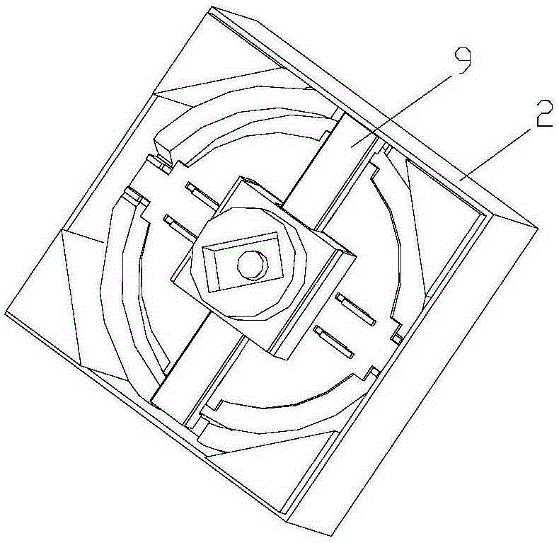
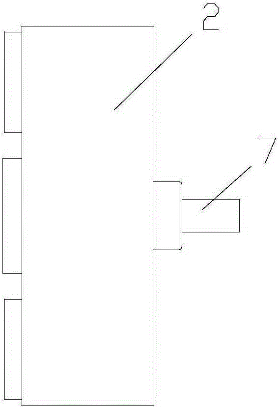
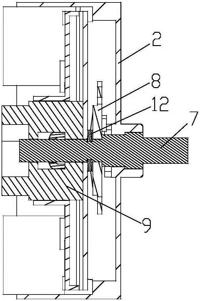
The invention provides an electrical switch rotation structure. The rotation structure comprises an upper cover, the upper cover is provided with a switch knob rod penetrating the upper cover, the switch knob rod is successively sleeved by a push plate and a limiting connection portion, the push plate and the switch knob rod are fixed, the limiting connection portion can move axially relative to the switch knob rod while rotating about the axis of the switch knob rod, and the circumference of the limiting connection portion and the circumference of the push plate are connected through multiple traction springs. The electrical switch rotation structure, through the design of traction by the multiple springs, a sufficient spring elastic force is generated, rapid rotation of the limiting connection portion is realized, an electrical switch contact sheet is driven to move rapidly, the opening time of the contact sheet is shortened, arcs are rapidly extinguished, and the springs with different elastic forces and materials with different strengths are selected along with the different electric power needing to be cut off so that convenience is provided for application of the product to different power occasions.

Description

technical field [0001] The invention relates to a rotating structure of an electric switch. Background technique [0002] The isolating switch based on the rotation control of the opening and closing of the moving contact piece and the static contact piece is very common, but when it is applied to a high-voltage direct current of about 1.5KV, because the direct current does not exceed the zero point, the arc stretches longer when it is disconnected, and the switch is required to have a relatively long Good arc extinguishing performance to reduce arcing. [0003] At present, when most disconnectors are used to break DC, most of them have the problem that the arc extinguishing time is too long or even unable to extinguish the arc, resulting in the burning of components. This is because many DC switches are slightly modified on the basis of AC switches, but AC has a zero-crossing point, so AC switches do not need to be specially designed for arc extinguishing problems, and the...

Claims


Application Information

Patent Timeline
Patent Type & Authority Applications(China)
IPC IPC(8): H01H19/10H01H19/08
CPCH01H19/08H01H19/10
Inventor 包海波
Owner SHANGHAI DEKAI ELECTRONICS CO LTD
Learn More