Positioning member for preventing detachment of axle

a technology of positioning member and axle, which is applied in the direction of door/window fittings, building locks, constructions, etc., can solve the problems of general inability to efficiently separate from the mounting seat, loss of thin nut, and inability to efficiently mount and dismount. , to achieve the effect of preventing undesired separation

Inactive Publication Date: 2009-11-26
ONLY INDAL CORP
View PDF17 Cites 24 Cited by
  • Summary
  • Abstract
  • Description
  • Claims
  • Application Information

AI Technical Summary

Benefits of technology

[0007]In accordance with the above described positioning member for preventing detachment of an axle, the positioning member forms a bent tab that extends downward from an edge of the plate-like body at a location adjacent to the straight slot.
[0008]In accordance with the above described positioning member for preventing detachment of an axle, sides...

Problems solved by technology

It is generally not easy to efficiently separate from the mounting seat at the time of dismounting and such an operation requires loosening of an adjustment bolt in order to replace the lower suspension member.
Thus, efficient mounting and dismounting is generally i...

Method used


Image

  • Positioning member for preventing detachment of axle
  • Positioning member for preventing detachment of axle
  • Positioning member for preventing detachment of axle

Examples


first embodiment

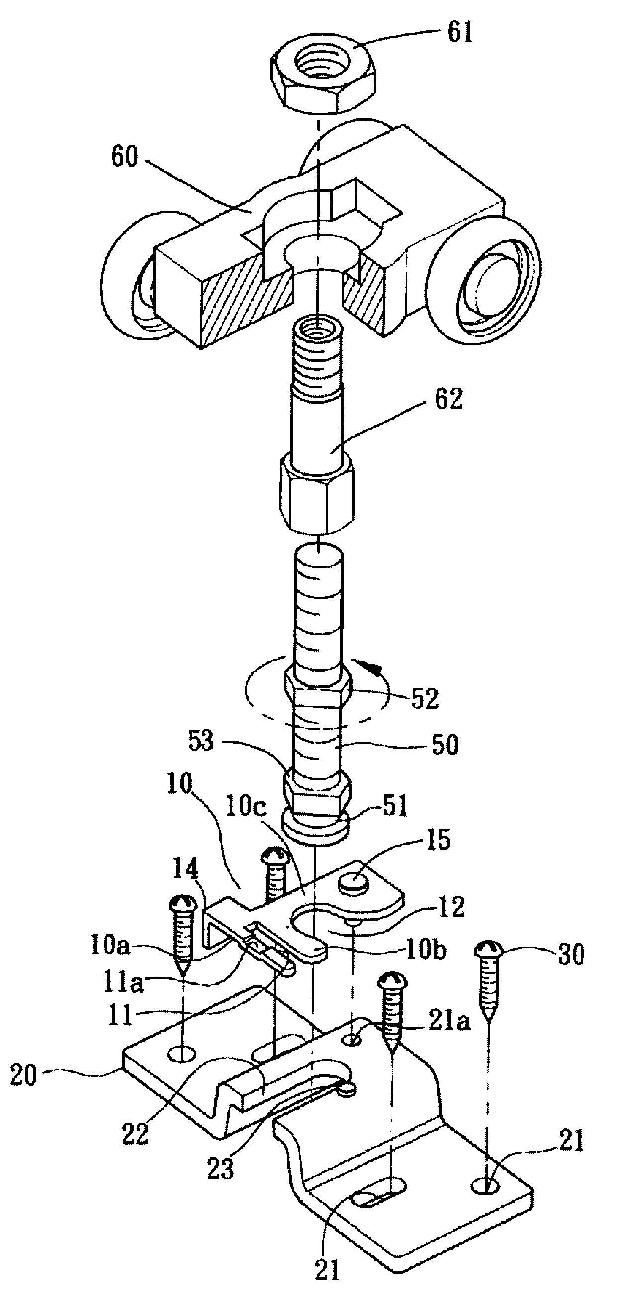
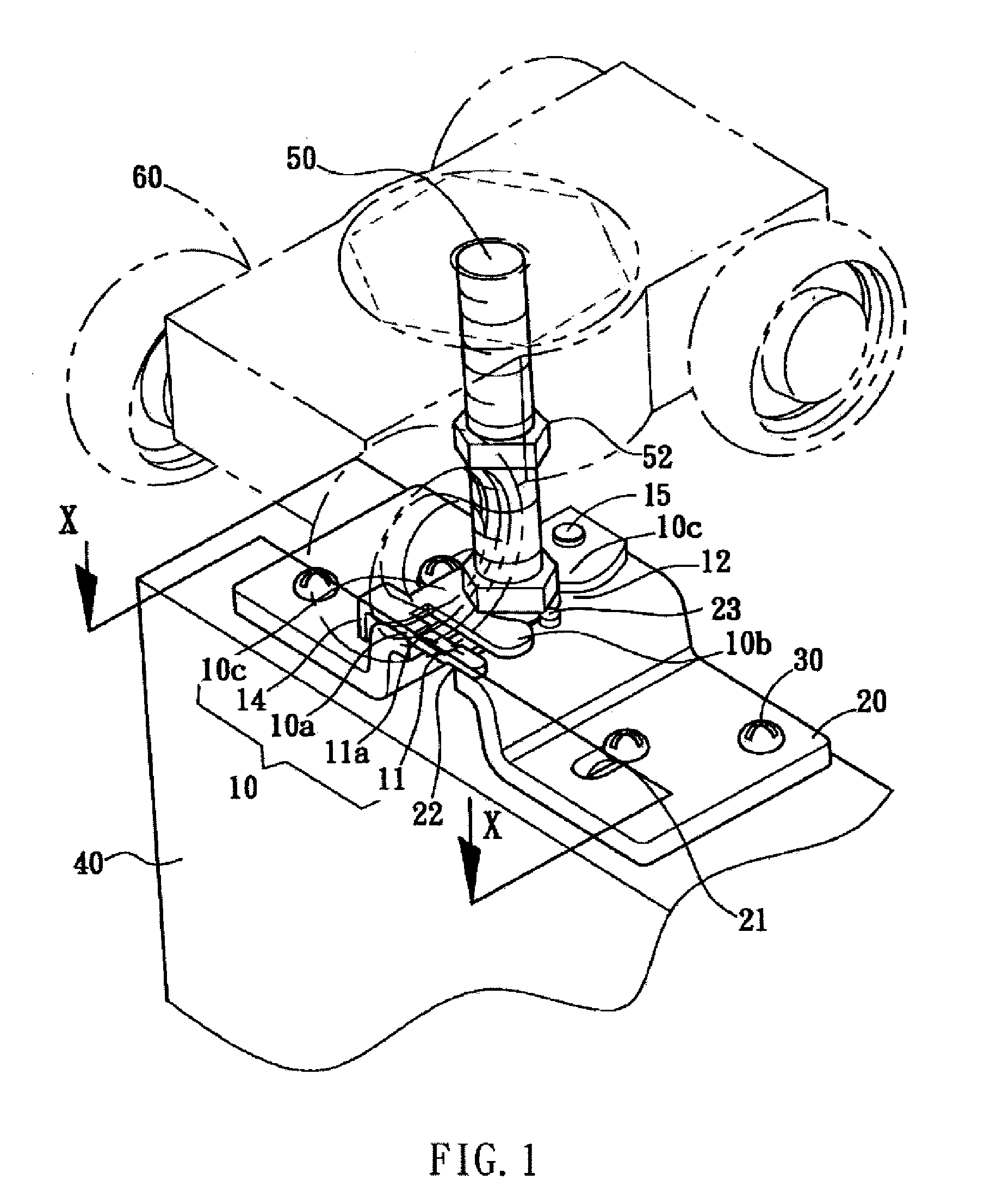
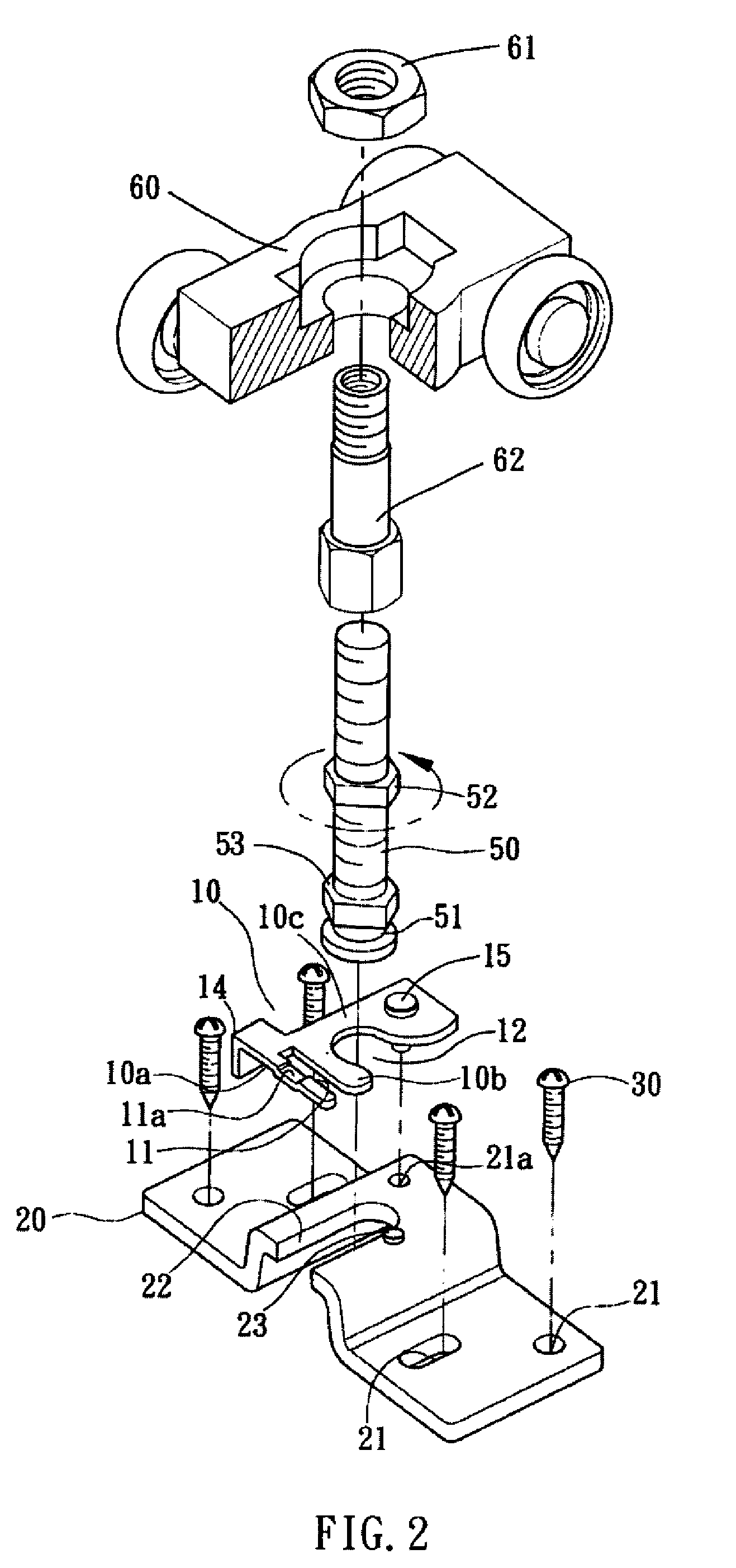
[0021]FIG. 1 shows a perspective view of a first embodiment in accordance with the present invention. FIG. 2 shows an exploded view of a positioning member in accordance with the present invention. FIG. 3 shows an enlarged view of a resilient fork-like fastener shown in FIG. 2. FIGS. 4 and 5 are cross-sectional views taken along line X-X of FIG. 1, illustrating the operation of the positioning member as viewed from the top side.

[0022]The above mentioned drawings show that the positioning member 10 provided in accordance with the present invention for preventing the detachment of an axle is coupled to a mounting plate 20. The mounting plate form a plurality of holes 21 that extends through the mounting plate for receiving the extension of threaded fasteners 30 to couple to an end face of an object 40. An upper adjustment nut 52 functions to adjust the distance between a roller seat 60 and the mounting plate 20 and to cooperate with a roller seat nut 61 and a roller seat bolt 62 to ef...

second embodiment

[0029]FIG. 6 shows a perspective view of a second embodiment of the positioning member in accordance with the present invention. The difference from the first embodiment is that the two shaped sections 10a, 10b on the opposite sides of the straight slot 11 are both provided with a stop 11a, 11b that is receivable into the elongate slot 22 to prevent undesired separation. Both stops make the respective shaped section showing a step-like configuration or they can be made corrugated (not shown). With the dual action of stopping by the two stops, the chance that the positioning member 10 gets loosened due to external impact is reduced. Further, in the second embodiment, the bent tab 14 is removed, whereby only shaped section 10a that is located at the outer side of the straight slot 11 can receive the force applied by the user to rotate the positioning member 10.


PUM


Abstract

A positioning member is coupled to a mounting plate, which defines a plurality of holes for receiving screws for connection with an end of an external object. An upper adjustment nut sets a distance between a roller seat and the mounting plate and to provide a securing function by cooperating with a roller seat nut and a roller seat bolt. The mounting plate forms in a central portion thereof an elongate slot for slidably receiving a neck of the axle therein. The positioning member includes a plate-like body forming a straight slot and an inclined slot for leading the neck therein and is provided with a rivet or a resilient fork-like fastener at one side of the inclined slot opposite to the straight slot to be fit into the a positioning hole defined beside the elongate slot for serving as a rotational axis of the positioning member.

Description

TECHNICAL FIELD OF THE INVENTION[0001]The present invention generally relates to a positioning member that prevents an axle of a roller-based suspension device from separation from a suspended object.DESCRIPTION OF THE PRIOR ART[0002]Various foldable doors or windows are available in the market. Some are used to isolate an area inside a house by providing a rail on a ceiling corresponding to the area to be isolated. The foldable door is provided with plural sets of roller based suspension devices, such as a slide door roller set or a suspension roller set. In this way, an area inside a house can be quickly isolated as desired to suit the needs for various applications and also to reduce the undesired external interference, as well as serving as means for privacy protection. After the use of the isolated area, the foldable door or a plurality of door panels can be moved to a corner to stack each other or to be removed, by which the original indoor space of the house resumes.SUMMARY O...

Claims


Application Information

Patent Timeline
IPC IPC(8): E05B15/02
CPCE05D15/26E05Y2201/64E05Y2600/528E05Y2600/53E05Y2600/60E05D15/0639E05Y2900/132Y10T292/696
Inventor TSAI, FAN-CHANG
Owner ONLY INDAL CORP
Why Eureka
Try Eureka