
Disk wheel

一种车轮、盘式的技术,应用在辐板式车轮、车轮、轮毂等方向,能够解决螺栓紧固部变形、难以确保螺栓紧固部强度等问题,达到确保必要强度、抑制残留应力的影响的效果

Inactive Publication Date: 2015-12-23
TOYOTA JIDOSHA KK
View PDF10 Cites 0 Cited by
  • Summary
  • Abstract
  • Description
  • Claims
  • Application Information

AI Technical Summary

Problems solved by technology

On the other hand, if the size of the bonded area between the resin part and the insert is suppressed, the bolt fastened part is likely to be deformed due to the excessive load received when the vehicle is running, so it may be difficult to secure the bolt fastened part. question of strength
Especially for a wheel with a large axle hub such as a wheel equipped with an in-wheel motor, the above-mentioned problem becomes more pronounced due to the increased diameter of the bolt fastening part of the disc wheel.

Method used


Image

  • Disk wheel
  • Disk wheel
  • Disk wheel

Examples


Embodiment Construction

[0016] Hereinafter, embodiments of the present invention will be described with reference to the drawings.

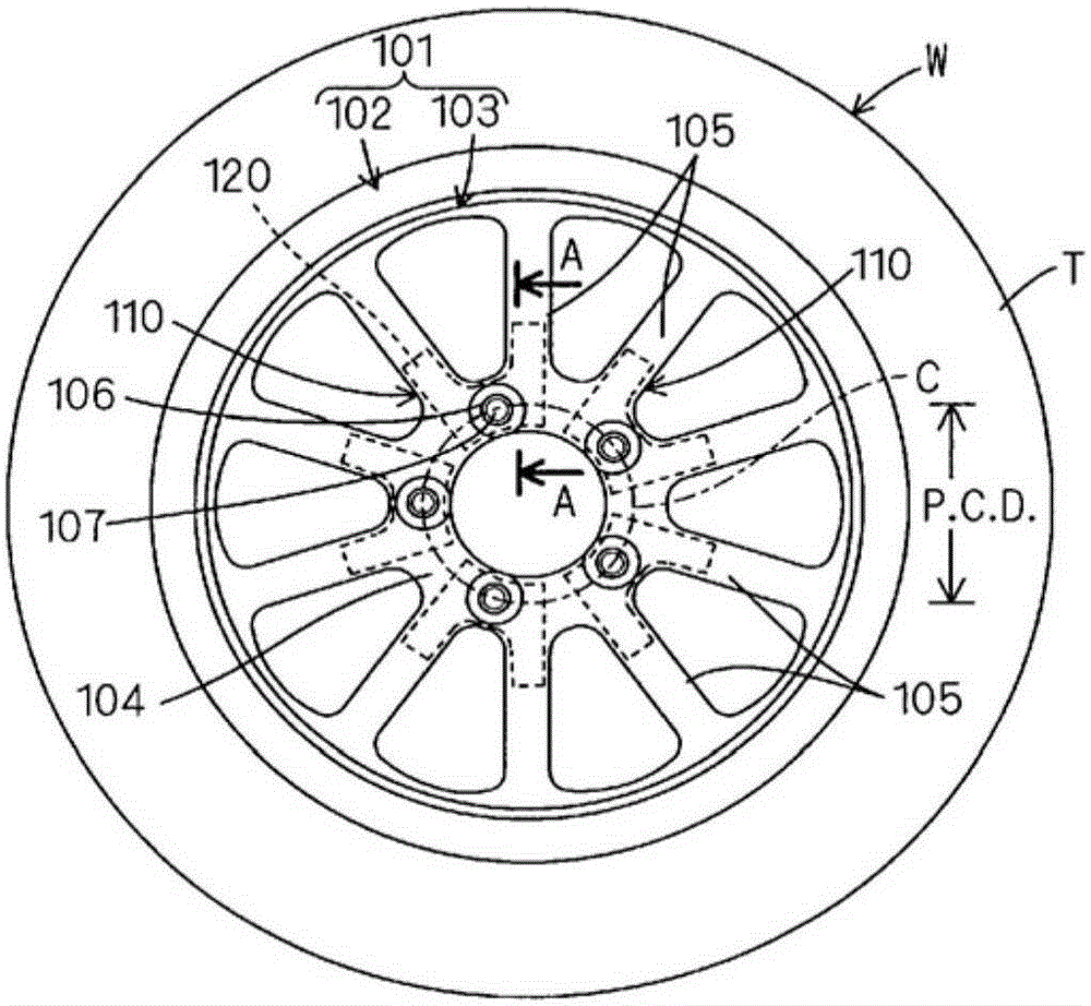
[0017] figure 1 A disc wheel 101 according to the present invention is shown in . By mounting a tire T on this disc wheel 101, a wheel W mounted on a vehicle is configured. The disc wheel 101 includes: a cylindrical rim 102 for holding a tire T; and a disc-shaped disc 103 joined to the rim 102 . That is, the disc wheel 101 has a so-called "one piece structure". The disk 103 further includes: a hub portion 104 attached to an axle hub (not shown); and spoke portions 105 radially protruding from the hub portion 104 . The disk 103 may be a type that does not include the spoke portion 105 . The hub portion 104 is provided with a plurality of bolt fastening portions 110 arranged annularly and coaxially along the circumferential direction of the disc 103 (circumferential direction of the disc wheel). Each bolt fastening portion 110 is provided with a bolt hole 106 through...


PUM


Abstract

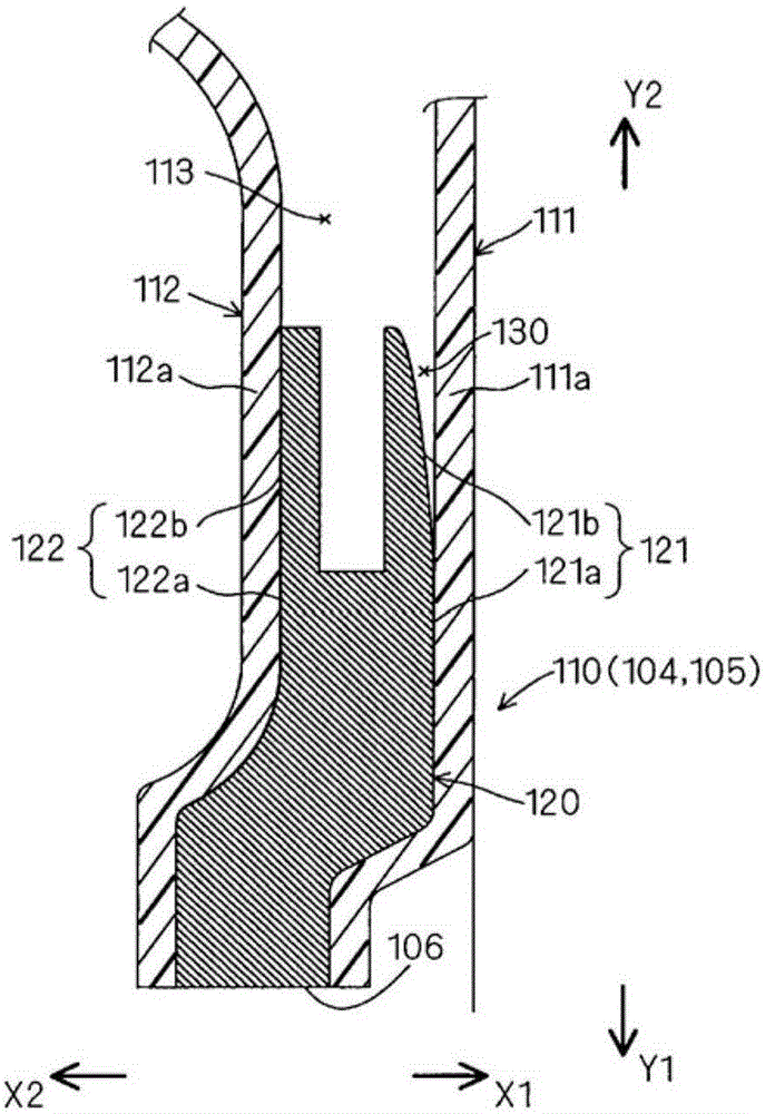
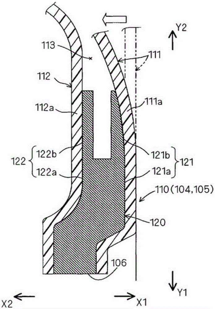
In this disk wheel, a metal insert member (120) is embedded in a resinous bolt-fastening part (110) having a bolt hole (106). The insert member (120) includes: an opposing surface (121) opposing a resin member (111) of the bolt-fastening part (110); a bonding area (121a) of the opposing surface (121), which bonds to the resin member (111); and a non-bonding area (121b) of the opposing surface (121), which does not bond to the resin member (111) but extends from the bonding area (121a) and bears the load when the resin member (111) deforms. It is thereby possible to provide a technique effective for suppressing the effect of residual stress after the resin member of the bolt-fastening part is molded, and for ensuring the strength needed in the bolt-fastening part.

Description

technical field [0001] The present invention relates to disc wheels for tyre-fitting. Background technique [0002] JP-A-2012-35568, JP-A-2002-293104, and JP-A-60-82402 all disclose disc wheels made of resin materials such as fiber-reinforced plastics. In this disc wheel, weight reduction is achieved by using a resin material, and on the other hand, the strength of the bolt fastening portion is secured by embedding metal inserts in the resin bolt fastening portion having bolt holes. [0003] In such a disc wheel, the resin part is usually bonded to the insert during molding, but in this case, due to the difference in the thermal expansion coefficients of the resin part and the insert part, the disc wheel is formed in the resin part after the disc wheel is molded. Excessive residual stress (thermal deformation stress). Therefore, in order to reduce the influence of the residual stress, it is necessary to suppress the size of the bonding area between the resin material and t...

Claims


Application Information

Patent Timeline
Patent Type & Authority Applications(China)
IPC IPC(8): B60B5/02B60B3/08B60B3/10
CPCB60B3/08B60B3/10B60B2360/10B60B2360/32B60B2360/348B60B2900/311B60B5/02B60B3/12B60B3/008B60B27/065B60B2900/111
Inventor 福留秀树
Owner TOYOTA JIDOSHA KK
Learn More