

Vehicle body forward portion structure
a technology for vehicle body and forward portion, which is applied in the direction of roof, transportation and packaging, vehicle arrangements, etc., can solve the problems of increased vehicle weight, increased number of parts, and inability to use welding, so as to ensure the necessary strength and lighten the front pillar portion
- Summary
- Abstract
- Description
- Claims
- Application Information
AI Technical Summary
Benefits of technology
Problems solved by technology
Method used
Image

Examples
second exemplary embodiment
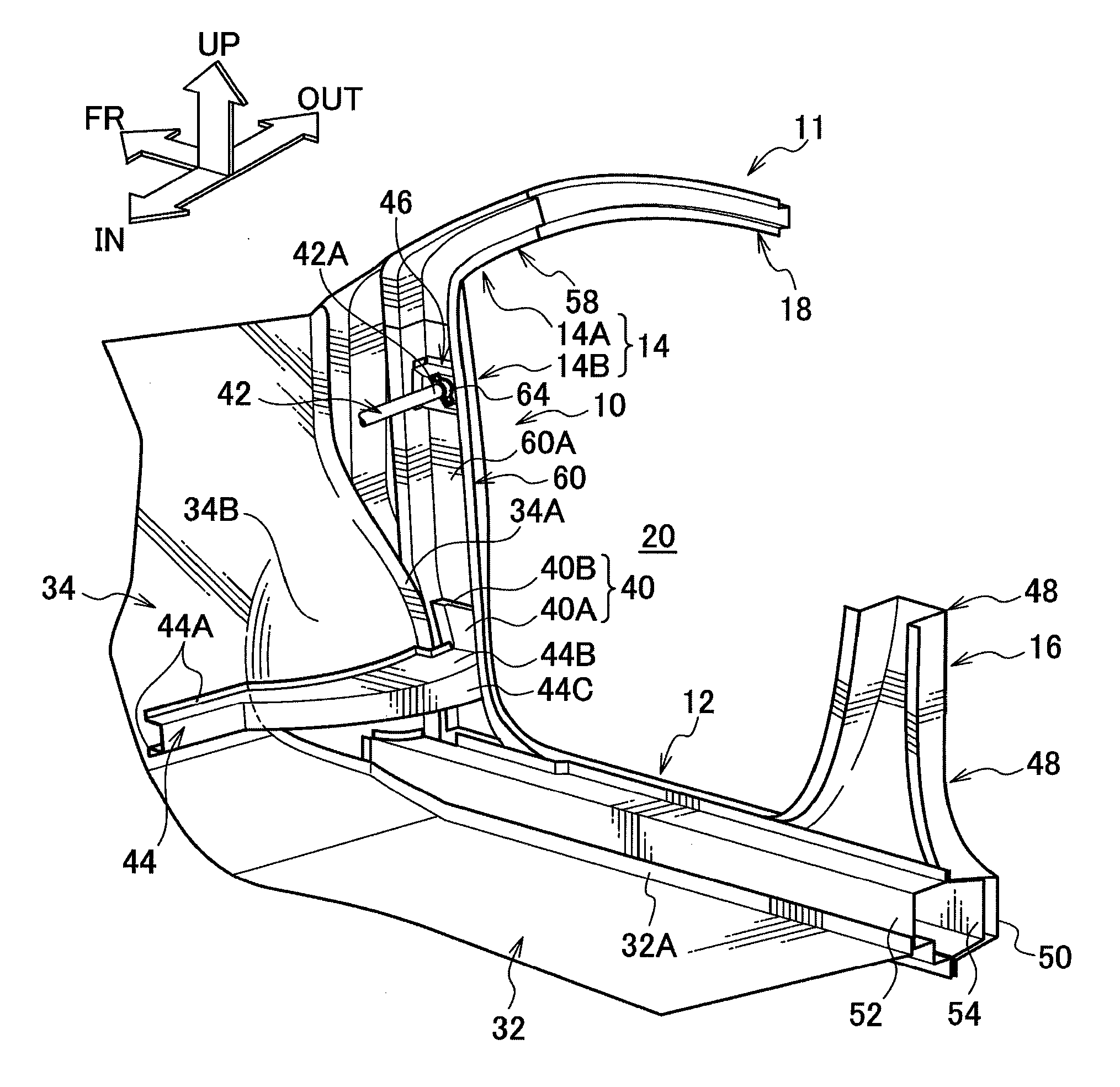
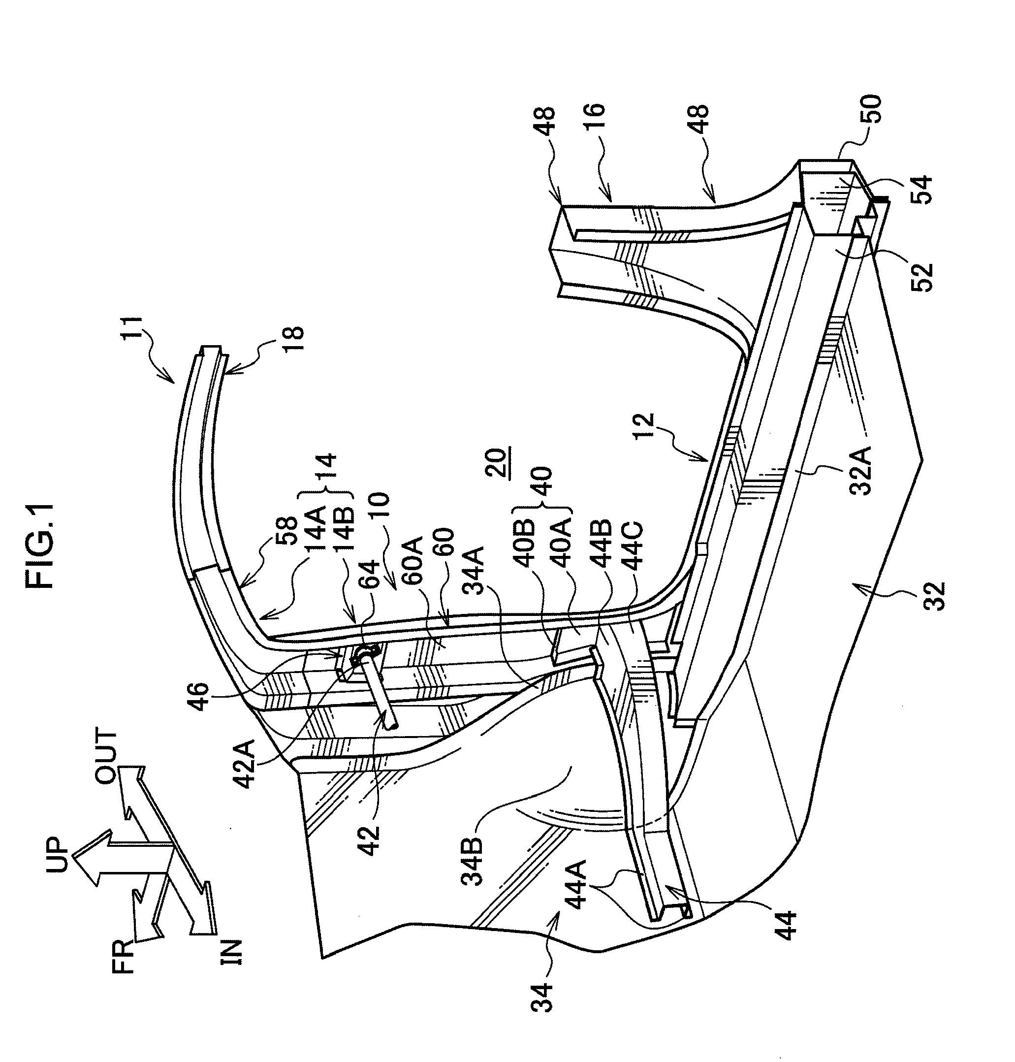
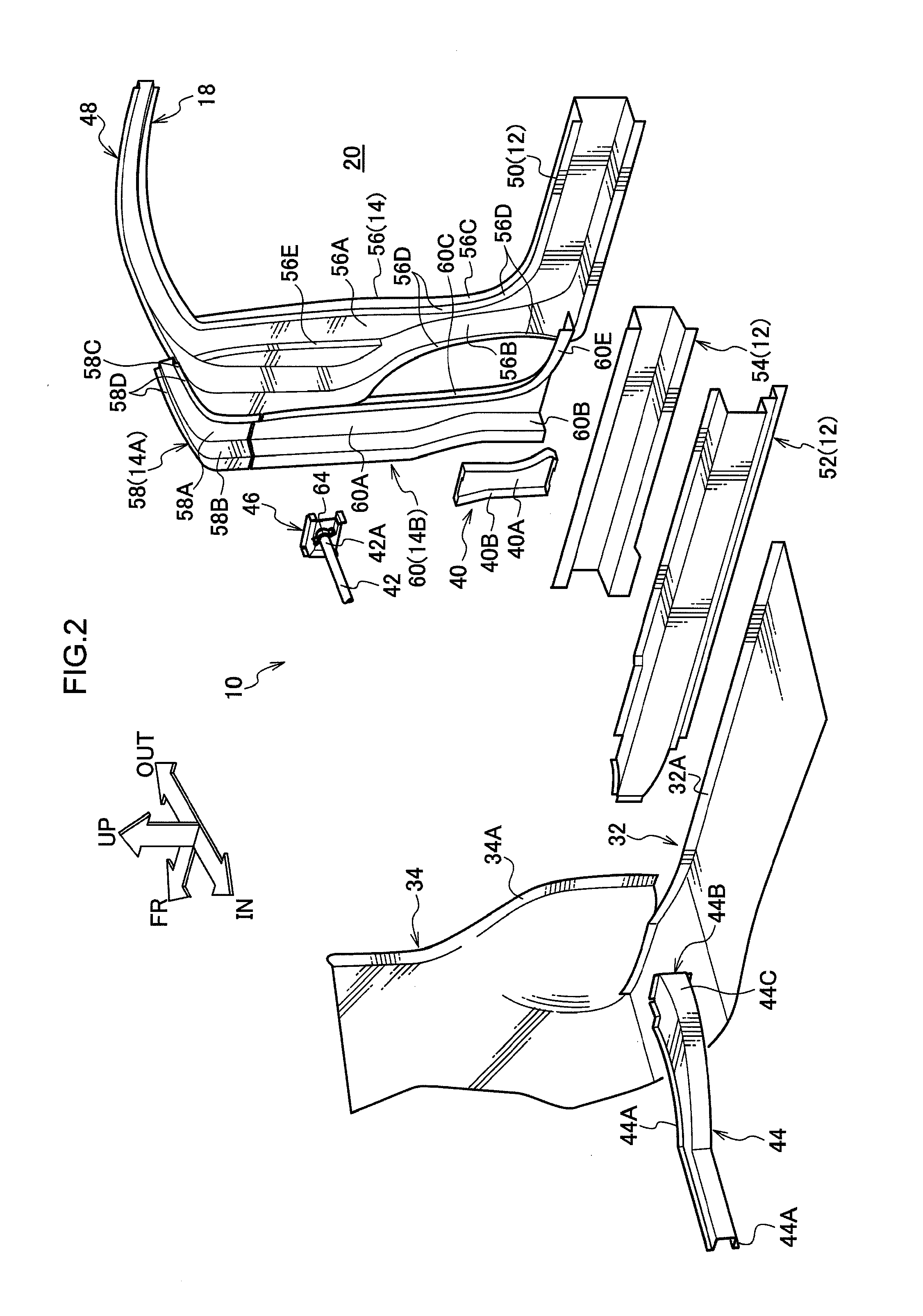
[0102]In FIG. 8, the main portion of vehicle body forward portion structure 70 according to the second exemplary embodiment is shown in perspective view corresponding to FIG. 6 of the first exemplary embodiment and, in FIG. 9, the main portion of vehicle body forward portion structure 70 is shown in cross section view corresponding to FIG. 7. As shown in these drawings, in vehicle body forward portion structure 70, rear wall 44C of dash cross member 44 is disposed in close proximity with bolts 72, which serve as fastening members. The configuration in this regard differs from vehicle body forward portion structure 10 in which rear wall 44C of dash cross member 44 is disposed in close proximity with rear wall 60C of pillar reinforcement lower 60.
[0103]Specifically, in vehicle body forward portion structure 70, door hinge 24 is fixed to the lower portion of front pillar lower 14B by fastening with bolts 72, which protrude into the inside of the open cross section portion of front pill...
third exemplary embodiment
[0107]In FIG. 10, the main portion of vehicle body forward portion structure 80 according to a third embodiment of the present invention is shown in plan sectional view corresponding to FIG. 4A of the first exemplary embodiment. As shown in this drawing, vehicle body forward portion structure 80 differs from vehicle body forward portion structures 10 and 70 in respect of the fact that the vehicle width direction outer end portion of dash panel 34 is joined to front wall 60B of pillar reinforcement lower 60.
[0108]Specifically, outer end portion 34C in a vehicle width direction of dash panel 34, which extends along a substantially vehicle width direction as seen in plan view, is joined to front wall 60B of pillar reinforcement lower 60 by spot welding. In this embodiment, outer end portion 34C in a vehicle width direction of dash panel 34, and respective front walls 60B and 56B of pillar reinforcement lower 60 and front pillar outer portion 56 are joined by spot welding in a three-lay...
fourth exemplary embodiment
[0113]In FIG. 11, the main portion of vehicle body forward portion structure 90 according to a fourth embodiment of the present invention is shown schematically in perspective view and, in FIG. 12A, the main portion of vehicle body forward portion structure 90 is shown schematically in plan view. As shown in these drawings, vehicle body forward portion structure 90 differs from vehicle body forward portion structures 10, 70, and 80 according to the first through third exemplary embodiments in respect of the fact that pillar brace 94 is provided as a connecting member between each front pillar lower 14B and dash cross member 92 in place of a configuration where dash cross member 44 directly spans between front pillar lowers 14B at both sides in a vehicle width direction.
[0114]Dash cross member 92 is formed in a hat shape with a cross section opening toward the vehicle front, and upper and lower flanges 92A are joined to the rear surface side of dash panel 34 at a portion positioned m...
PUM
 Abstract
Description
Claims
Application Information