
Pipeline regeneration pipe

a technology for regenerating pipes and pipes, applied in the direction of sewer pipes, shaft equipment, shaft linings, etc., can solve the problems of insufficient flow capacity, collapse of road surface, and large size of pipes produced to be used in this method, and achieve the effect of ensuring the necessary strength

Active Publication Date: 2015-04-28
KANA FURETSUKUSU KOOHOREESHON
View PDF30 Cites 0 Cited by
  • Summary
  • Abstract
  • Description
  • Claims
  • Application Information

AI Technical Summary

Benefits of technology

The present invention provides a pipeline regeneration pipe that can ensure the necessary strength without the need for grouting. This means that the pipe itself is designed to be strong and durable enough to withstand the harsh environments and stresses that it will face during use. This improves the overall quality and reliability of the pipeline, reducing the likelihood of failures and accidents.

Problems solved by technology

In cases where a sewer pipe has been buried in soil for many years and aged to be deteriorated in load resistance capacity or water shutoff capacity, there arise problems such as collapse of a road surface and insufficient flow capacity.
However, the pipe making method requires dedicated construction facilities such as the pipe forming machine, and construction in this method needs to be executed by a skilled mechanic.
Although the casing pipe construction method does not require such a pipe forming machine, the pipes produced to be used in this method are large in size and thus cannot be easily handled in a narrow manhole.
In addition, both of these construction methods require connection work upon forming into a pipe shape in an existing pipe, and such work takes long time in order to enhance sealing performance at the connected parts, which is problematic.

Method used


Image

  • Pipeline regeneration pipe
  • Pipeline regeneration pipe
  • Pipeline regeneration pipe

Examples


Embodiment Construction

[0026]An embodiment of the present invention is described in detail below with reference to the drawings.

[0027]1. Structure of Drain Pipe

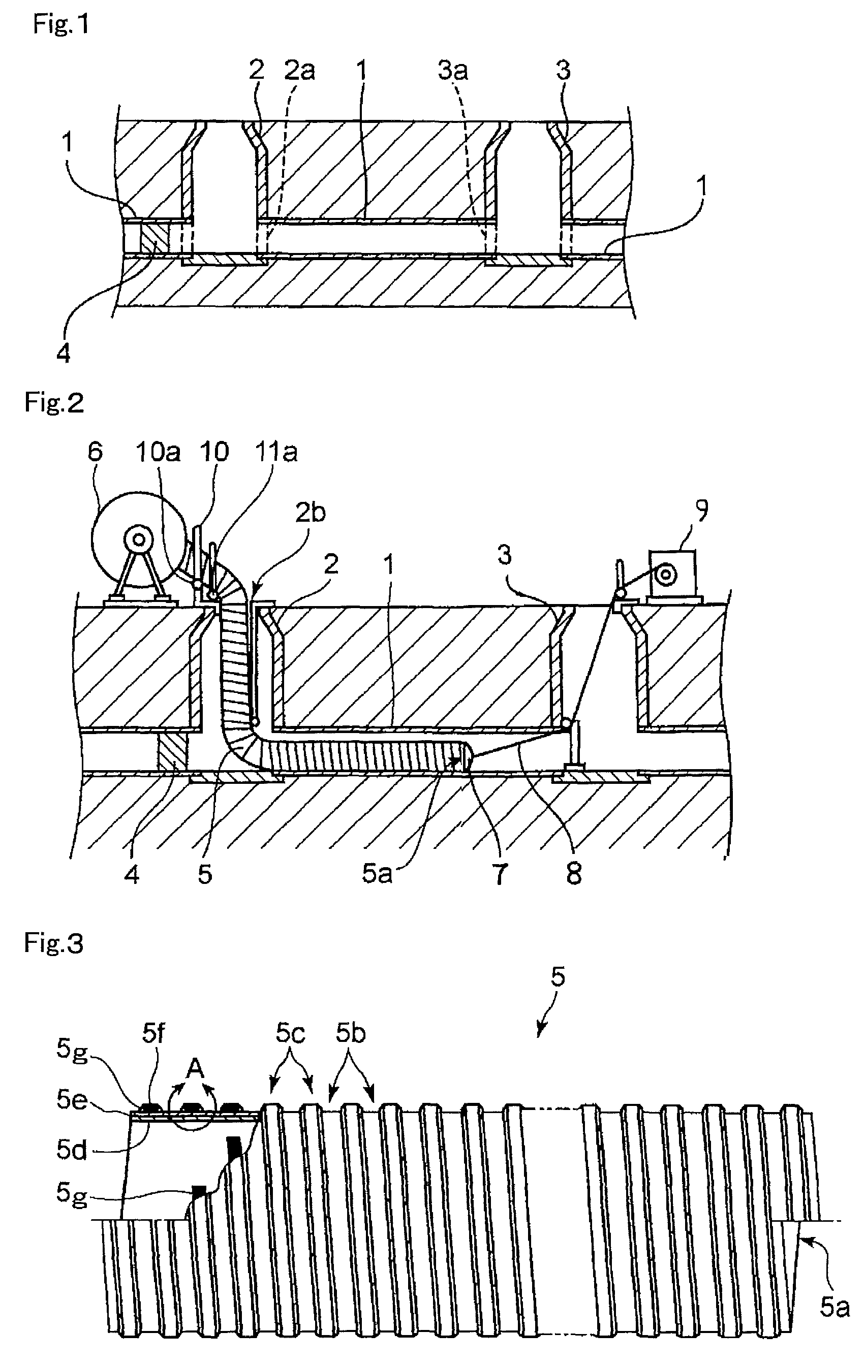
[0028]FIG. 1 shows the structures of existing drain pipes, to which a pipeline regeneration pipe (hereinafter, abbreviated as regeneration pipe) according to the present invention is applied, as well as the structures of manholes.

[0029]In this figure, a plurality of existing drain pipes 1 buried in soil are often made of concrete. The drain pipes 1 are each connected to openings 2a and 3a, which are respectively provided at lower ends of a left manhole 2 and a right manhole 3, for example, being located on a drain route.

[0030]Upon regeneration of one of the drain pipes 1, the drain pipe 1 is inspected preliminarily to check if there is no difficulty in insertion of a regeneration pipe. The drain pipe 1 is washed if necessary, in which case a water shutoff valve 4 is attached.

[0031]2. Method of Inserting Regeneration Pipe

[0032]FIG. 2 shows a method ...


PUM


Abstract

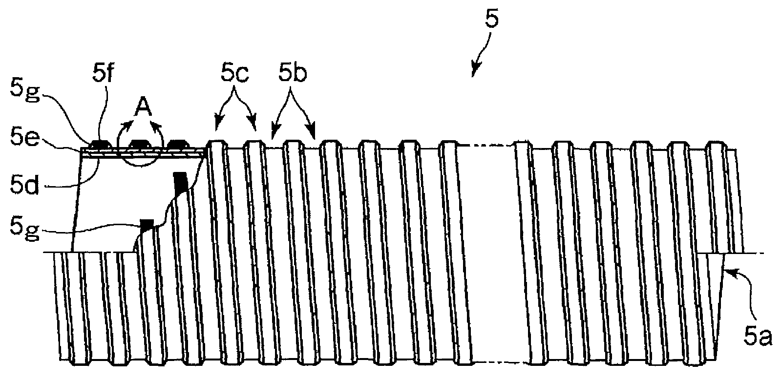
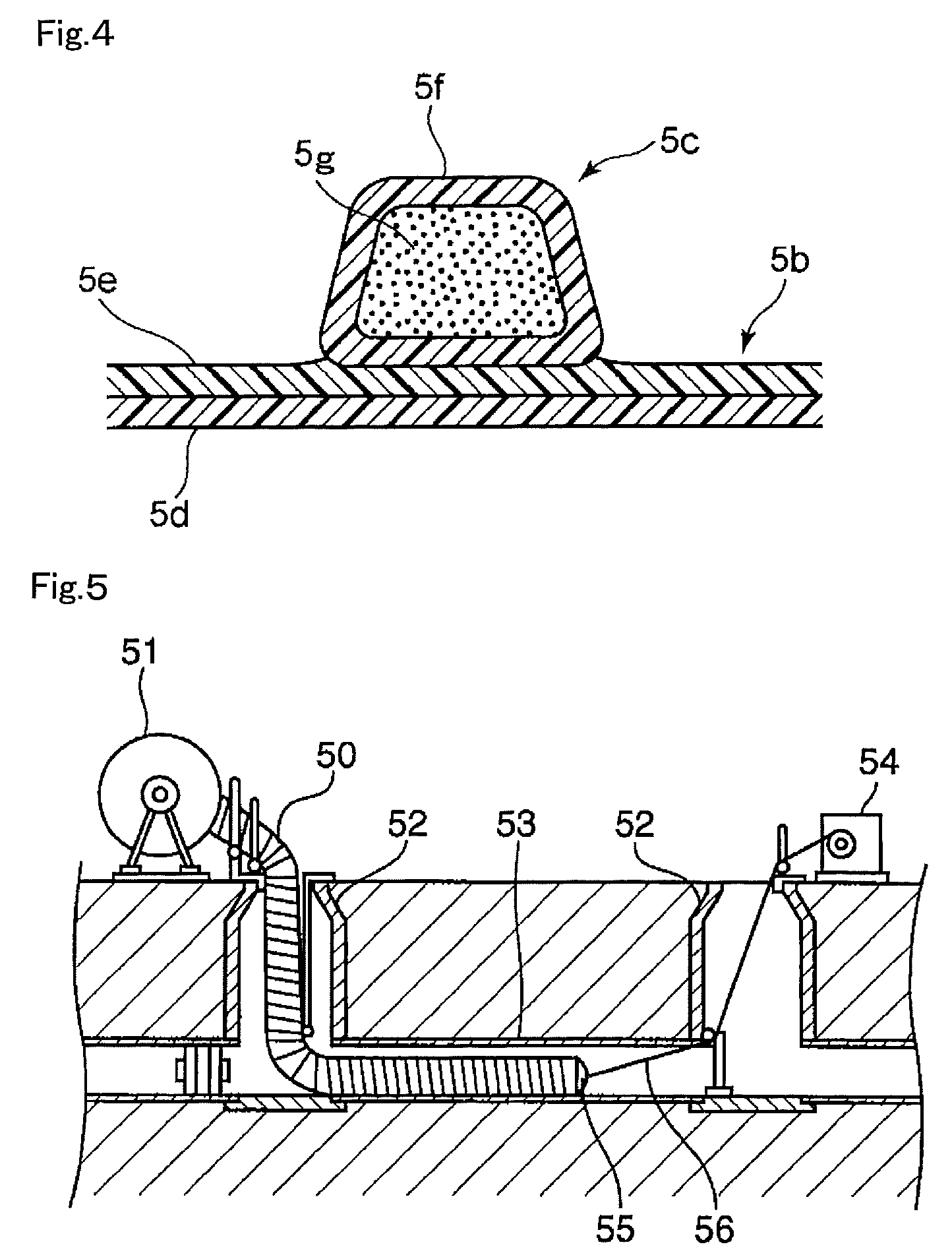
A pipeline regeneration pipe, with which necessary strength can be ensured by way of the inserted regeneration pipe itself without the necessity of grouting, includes an inner wound flexible resin layer 5d which constitutes the inner layer of a straight pipe part 5b, an outer wound flexible resin layer 5e laminated on the outer surface of the inner wound flexible resin layer and constitutes the outer layer of the straight pipe part, and a protruded rim part 5c helically formed on the outer surface of the outer wound flexible resin layer, the protruded rim part 5c being configured by a rigid-resin core 5g helically wound, and a core-covering part 5f integrated with the outer wound flexible resin layer so as to surround the rigid-resin core.

Description

TECHNICAL FIELD[0001]The present invention relates to a pipeline regeneration pipe inserted into a pipeline of any type, such as a sewer pipe, which has been buried in the ground and aged, so as to regenerate the pipeline.BACKGROUND ART[0002]In cases where a sewer pipe has been buried in soil for many years and aged to be deteriorated in load resistance capacity or water shutoff capacity, there arise problems such as collapse of a road surface and insufficient flow capacity.[0003]In order to solve such problems, there has been proposed and embodied a method of repairing a drain pipe, in which an aged sewer pipe is used as a support and a new resin pipe is inserted thereinto to serve as a drain pipe.[0004]There are various methods of repairing a drain pipe, including the pipe making method, for example, in which a rigid vinyl chloride member in a belt shape is supplied into a manhole, and the rigid vinyl chloride member in the belt shape, which is formed into a pipe shape at an inlet...

Claims


Application Information

Patent Timeline
Patent Type & Authority Patents(United States)
IPC IPC(8): F16L55/16E03F3/06F16L11/02F16L11/15F16L11/16F16L11/24F16L55/165
CPCF16L11/02F16L11/16F16L55/1652F16L55/1656E03F3/06F16L11/15F16L11/24E03F2003/065
Inventor KANAO, SHIGEKI
Owner KANA FURETSUKUSU KOOHOREESHON
Learn More