Stomach tube for digestive system department

A gastroenterology and gastric tube technology, which is applied in the medical field, can solve the problems of inability to synchronize fluid intake and drainage, increase the difficulty of treatment operations, and difficult to adjust the insertion depth, so as to improve the efficiency of intubation, the comfort of treatment, and the improvement of Effective intubation efficiency and simple structure

Inactive Publication Date: 2015-12-30
CHENGDU SHUYUNDA TECH CO LTD
View PDF0 Cites 1 Cited by
  • Summary
  • Abstract
  • Description
  • Claims
  • Application Information

AI Technical Summary

Problems solved by technology

[0002] At present, when a doctor in a hospital performs a gastric examination on a patient, he generally checks the insertion of a gastric tube. The insertion of a general gastric tube will cause great discomfort to people, and it is difficult to adjust the insertion depth. In the prior art, due to gastric There is only one tube, and both the liquid intake and the liquid discharge need to be transported by this gastric tube, so the liquid intake and liquid discharge cannot be carried out synchronously, the efficiency of gastric lavage is low, and the pain of the patient is increased. In order to solve the above problems, there is an existing gastric tube, although This kind of gastric tube is equipped with two tubes in and out, but this double-tube gastric tube greatly increases the volume of the gastric tube, thereby increasing the difficulty of the treatment operation and increasing the pain of the patient

Method used


Image

  • Stomach tube for digestive system department

Examples


Embodiment Construction

[0014] The technical solutions in the embodiments of the present invention will be clearly and completely described below in conjunction with the accompanying drawings in the embodiments of the present invention. Obviously, the described embodiments are only a part of the embodiments of the present invention, rather than all the embodiments. Based on the embodiments of the present invention, all other embodiments obtained by those of ordinary skill in the art without creative work shall fall within the protection scope of the present invention.

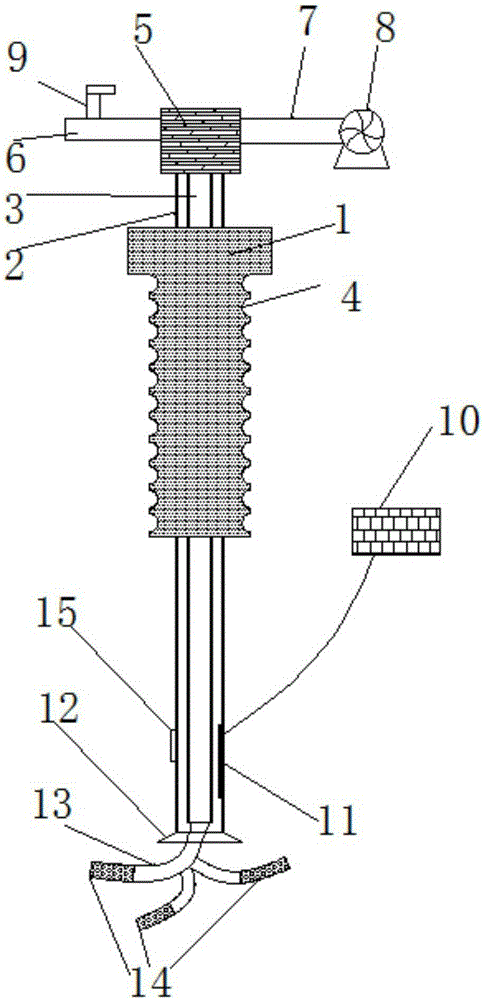
[0015] See figure 1 In the embodiment of the present invention, a gastrointestinal tube for gastroenterology includes a sleeve 1, a drainage tube 2 and an inlet tube 3. The materials of the sleeve 1, the drainage tube 2 and the liquid inlet tube 3 are all PVC Material, the inside of the discharge pipe 2 is provided with a liquid inlet pipe 3, and a liquid discharge gap is provided between the liquid discharge pipe 2 and the liquid inlet ...


PUM


Abstract

The invention discloses a stomach tube for the digestive system department. The stomach tube comprises a sleeve, a liquid discharging tube and a liquid inlet tube. The liquid inlet tube is arranged on the inner side of the liquid discharging tube. A connecting block is connected with the upper end of the liquid discharging tube and the upper end of the liquid inlet tube. An upper end opening of the liquid discharging tube is connected with a material discharging receiving tube. A liquid discharging pump is arranged at the tail end of the material discharging receiving tube. A material inlet receiving tube is connected with the upper end of the liquid inlet tube. A throttle valve is arranged on the material inlet receiving tube. Liquid guide hoses are arranged at the lower end of the liquid inlet tube. Water dividing tubes are connected with the tail ends of the liquid guide hoses. A liquid sucking disc is arranged at a lower end opening of the liquid discharging tube. A depth sensor is arranged at the lower end of a tube body of the liquid discharging tube and connected with a controller. An observing probe is arranged on the side, opposite to the depth sensor, of the liquid discharging tube. The sleeve is arranged on the outer side of the liquid discharging tube. A corrugation groove is formed in the surface of the sleeve. The stomach tube is simple and reasonable in structure; the cleaning effect of inlet liquid on the intestines and the stomach is improved, liquid feeding and liquid discharging are carried out synchronously, and the tube insertion efficiency of a medical worker and the treatment comfort degree are further improved.

Description

Technical field [0001] The invention relates to the field of medical technology, in particular to a gastric tube for gastroenterology. Background technique [0002] At present, when doctors in hospitals perform gastric examinations on patients, they will generally be inserted into the gastric tube to check. General gastric tube insertion will cause great discomfort and it is not easy to adjust the insertion depth. In the prior art, due to the stomach There is only one tube, and this gastric tube is needed for liquid inflow and outflow. Therefore, the inflow and outflow cannot be carried out simultaneously. The efficiency of gastric lavage is low and the patient's pain is increased. In order to solve the above problems, there is a gastric tube. This type of gastric tube is provided with two inlet and outlet tubes, but this double-tube type gastric tube greatly increases the volume of the gastric tube, thereby increasing the difficulty of treatment operation and also increasing the...

Claims


Application Information

Patent Timeline
IPC IPC(8): A61M25/14A61B1/273A61B1/04
Inventor 谭博文
Owner CHENGDU SHUYUNDA TECH CO LTD
Why Eureka
Try Eureka