Scaffold

A scaffolding and platform technology, applied in the field of scaffolding, can solve problems such as low operating efficiency, achieve the effects of occupying a small space, saving operators and time, and improving operating efficiency

Active Publication Date: 2015-12-30
王军伟 +2
View PDF10 Cites 5 Cited by
  • Summary
  • Abstract
  • Description
  • Claims
  • Application Information

AI Technical Summary

Problems solved by technology

[0003] In order to solve the problem that the current scaffold needs to be installed at the construction site, resulting in low operating efficiency, the present invention proposes a scaffold, which has the function of folding, without the need for installation at the construction site, and can be used directly by unfolding the scaffold of the present invention. It saves the time of installing scaffolding and improves the working efficiency

Method used


Image

  • Scaffold
  • Scaffold
  • Scaffold

Examples


Embodiment 1

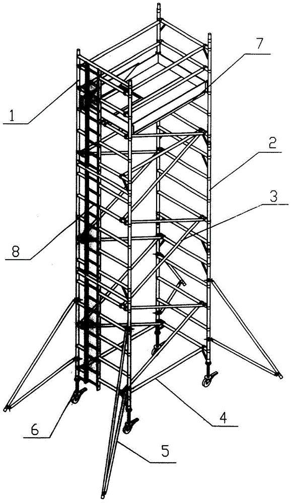
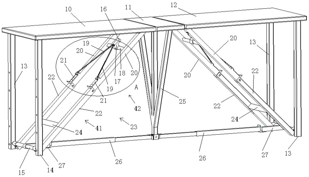
[0028] Such as figure 2 As shown, the scaffolding of this embodiment includes a first platform 10, a second platform 11 and a third platform 12, as shown in the figure, the first platform 10, the second platform 11 and the third platform 12 are all plate structures, using During scaffolding in this embodiment, the operator stands on the first platform 10 , the second platform 11 or the third platform 12 to perform operations. The first platform 10 and the third platform 12 are located at both sides of the second platform 11, and the first platform 10 and the third platform 12 are respectively connected with the second platform 11 by hinges, so that the first platform 10, the second platform 11 and The third platform 12 can be folded.

[0029] One end of the first platform 10 near the second platform 11 is provided with a cable-stayed support unit 23, and the other end is provided with two first support rods 13, and a crossbeam 15 is connected between the two first support ro...

Embodiment 2

[0036] The difference between this embodiment and the first embodiment is that a detachable support assembly is added, and the first support rod 13 is a telescopic rod. The detachable supporting component supports the scaffolding of this embodiment, so as to further increase the stability of the scaffolding of this embodiment and increase the weight it can bear. Moreover, the first support rod 13 is a telescopic rod, so by adjusting the length of the first support rod 13, the height of the scaffold in this embodiment can be adjusted to meet the needs of different working conditions on site.

[0037] Such as Figure 6-Figure 8 As shown, the detachable support assembly includes two sleeve parts 33, the sleeve parts 33 are triangular in structure, and the two vertices of the sleeve parts 33 are provided with sleeves 32 that cooperate with the first support rod 13. The cylinder 32 is sleeved on the first support rod 13, and the other apex is connected with the fixed rod 31, and t...


PUM


Abstract

The invention belongs to the technical field of building construction, aims at solving the problems that a current scaffold needs to be installed at the construction site, so that the working efficiency is low and provides a scaffold. The scaffold comprises a first platform, a second platform and a third platform, the bottom face of the first platform and the bottom face of the third platform are each provided with an inclined-pulling supporting unit, each inclined-pulling supporting unit comprises an inclined-pulling component and a containing component, and each inclined-pulling component comprises a connection tube, slide blocks and two inclined-pulling tubes; each containing component comprises two containing tubes; each slide block is located at the end, connected with the corresponding containing tube, of the corresponding inclined-pulling tube, slide grooves are formed in the two sides of each slide block, and the slide blocks are connected with a rotary sleeve through connection ropes; a first spring is arranged at the end, connected with the corresponding containing tube, of each inclined-pulling tube, and each first spring is connected with the bottom of the corresponding slide block. The scaffold can be folded, the height of the scaffold can be adjusted, the scaffold can be directly unfolded to be used, and working efficiency is improved.

Description

technical field [0001] The invention belongs to the technical field of building construction, and in particular relates to a scaffold. Background technique [0002] Scaffolding refers to the support set up on the construction site for operators to work at a higher position. Scaffolding usually needs to be erected on the construction site. The traditional erection method is to connect steel pipes of various lengths one by one through fasteners. This construction method uses a large number of fasteners and steel pipes, and the workload is large. , It takes a long time, and it is built on site, which will have an impact on the construction period. Such as figure 1 As shown, the patent No. 200420094998 discloses a scaffold, which includes a left door frame 1, a right door frame 2, a diagonal brace 3, a cross brace 4, an outer support frame 5, and an adjustable brake roller 6, pedal 7 and ladder frame 8. Diagonal struts 3 and cross struts 4 are used to connect left gantry 1 a...

Claims


Application Information

Patent Timeline
Patent Type & Authority Applications(China)
IPC IPC(8): E04G1/34
Inventor 王军伟王军龙王五会
Owner 王军伟
Why Eureka
Try Eureka