
Touch detection method and device for touch display screen

A technology of touch display and touch detection, which is applied in the direction of static indicators, data processing input/output process, instruments, etc., and can solve the problem of insufficient charging time of the touch display

Active Publication Date: 2015-12-30
CHONGQING BOE OPTOELECTRONICS +1
View PDF5 Cites 10 Cited by
  • Summary
  • Abstract
  • Description
  • Claims
  • Application Information

AI Technical Summary

Problems solved by technology

In order to solve the problem of insufficient charging time of the above-mentioned touch screen, the present invention provides a new touch detection method and device

Method used


Image

  • Touch detection method and device for touch display screen
  • Touch detection method and device for touch display screen
  • Touch detection method and device for touch display screen

Examples


Embodiment approach

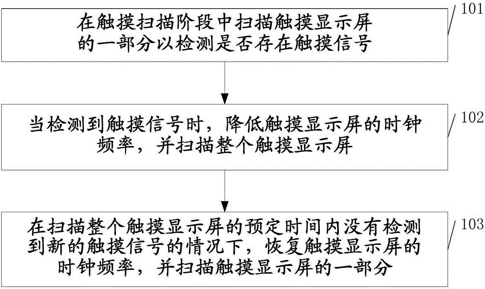
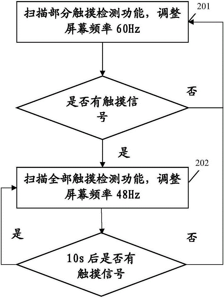
[0021] According to one embodiment, the method further includes: step 103, if no new touch signal is detected within the predetermined time of scanning the entire touch display screen, restore the frame rate of the touch display screen, and scan the part. The predetermined time can be set according to specific needs, for example, 10s.

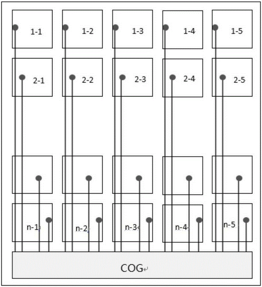
[0022] According to an implementation manner, the step of scanning a part of the touch display screen includes: scanning a part of a row array, a column array, a non-adjacent array or a part of the touch display screen.

[0023] According to one embodiment, the step of scanning part of the row or column array of the touch display screen includes: alternately scanning the odd-numbered and even-numbered rows or odd-numbered columns and even-numbered column arrays of the touch display screen in different frames.

[0024] According to an implementation manner, the step of reducing the frame rate of the touch display screen includes, for example, r...


PUM


Abstract

The invention provides a touch detection method and device for a touch display screen. The scanning time for the touch display screen in each frame comprises a display scanning stage and a touch scanning stage. The method includes the steps that a part of the touch display screen is scanned in the touch scanning stages to detect whether a touch signal exists or not; when the touch signal is detected, the frame rate of the touch display screen is reduced, and the whole touch display screen is scanned. In this way, the charging time of a panel is guaranteed while the display function and the touch detecting function are reused.

Description

technical field [0001] The present invention generally relates to the field of touch screens, and in particular to a touch detection method and device for touch screens. Background technique [0002] At present, with the application of LCD products more and more widely, various LCD products with touch functions are also more and more valued by consumers, especially the popularization of smart phones, which makes the demand and usage of touch screens continue to increase. At present, the widely used touch method is capacitive, which is divided into on-cell and in-cell. Fullincell is a kind of incell, and the capacitance sensing method adopted is self-capacitance sensing. Due to the method of adding metal leads on the array, it has the advantages of little influence on the sensing electrodes by gray scale conversion, high signal-to-noise ratio, and low resistance. However, due to the large number of touch electrodes and the source (source) Shared IC with touch, adopts time-sh...

Claims


Application Information

Patent Timeline
IPC IPC(8): G06F3/044
CPCG06F1/3262G06F3/04166G06F3/0443G09G3/3677G09G2310/08G06F3/0412G09G2310/0251G09G2310/0297G09G2354/00
Inventor 徐波侯帅王武高贤永梁利生伏思庆许益祯尚飞邱海军
Owner CHONGQING BOE OPTOELECTRONICS
Learn More