On-pillar distribution transformer with internal protection function

A technology for distribution transformers and protection functions, applied in the field of distribution transformers, can solve problems such as unguaranteed power supply quality and reliability, rising management costs, and increased probability of transformer failure, so as to avoid operation, improve the reliability of power supply, and prevent the effect of excessive oil temperature

Inactive Publication Date: 2015-12-30
国网北京市电力公司电力科学研究院 +6
View PDF6 Cites 0 Cited by
  • Summary
  • Abstract
  • Description
  • Claims
  • Application Information

AI Technical Summary

Problems solved by technology

[0002] Ordinary pole-mounted distribution transformers adopt the traditional protection method of installing drop-out fuses on the external high-voltage side and circuit breakers on the low-voltage side. This protection method will be affected by the external environment and human factors, resulting in reduced protection reliability. When the transformer When the internal oil temperature is too high or the oil level drops, it will not be protected, which will increase the probability of transformer failure, and the quality and reliability of power supply will not be guaranteed.
In addition, this traditional protection method only uses phase separation to cut off the fault, which may easily cause the transformer to run without phase; the fuse needs to be replaced after the high-voltage drop-out fuse operates, the operation is complicated, the power supply is restored slowly, and the management cost increases

Method used


Image

  • On-pillar distribution transformer with internal protection function
  • On-pillar distribution transformer with internal protection function
  • On-pillar distribution transformer with internal protection function

Examples


Embodiment Construction

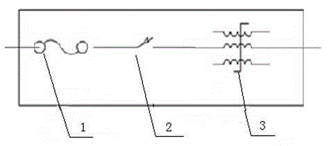
[0020] The pole-mounted distribution transformer with built-in protection function of the present invention, like the existing pole-mounted distribution transformer, also includes a high-voltage incoming line, an oil tank, a high-voltage winding 3 and an iron core upper yoke 4 . Its protection adopts the method of setting high-voltage backup fuse 1 and three-phase magnetic latching breaker 2 in the fuel tank, such as figure 1 As shown, the backup fuse 1 is directly connected to the insulating sleeve of the high-voltage incoming line and the three-phase magnetic latching breaker 2 , and the three-phase magnetic latching breaker 2 is connected to the high-voltage winding 3 .

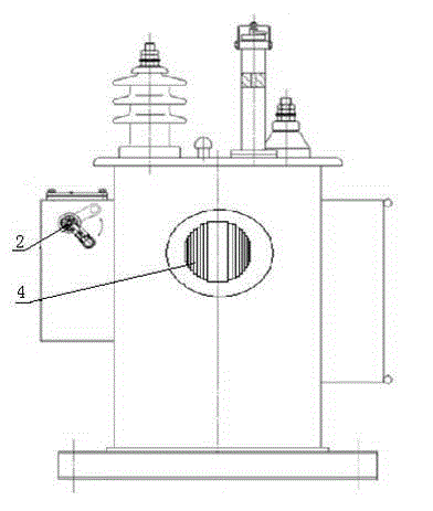
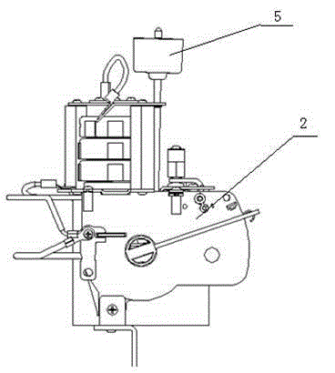
[0021] The three-phase magnetic latching breaker 2 is set on the inner side of the oil tank of the distribution transformer on the column, such as figure 2 As shown, its position is higher than the top of the upper core yoke 4 of the pole-mounted distribution transformer. The oil temperature at the top o...


PUM


Abstract

An on-pillar distribution transformer with an internal protection function comprises a high-voltage incoming line, an oil tank and a high-voltage winding, wherein a backup fuse and a three-phase magnetic latching interrupter are arranged in the oil tank; the backup fuse is in direct connection with the insulating sleeve of the high-voltage incoming line and the three-phase magnetic latching interrupter; the three-phase magnetic latching interrupter is connected with the high-voltage winding, arranged on an inner side surface of the oil tank, and higher than the top of an iron core upper yoke of the on-pillar distribution transformer. The on-pillar distribution transformer has the advantages that two-stage protection for overloading and breakdown, over-high oil temperature protection, lower-low oil level locking and manual closing function, load current breaking and closing function and the like are realized; equipment replacement is avoided during overload protection, so that repeated use is realized, power supply is restored fast, and the management cost is low; phase-failure operation of the transformer is avoided, so as to reduce the failure rate of the transformer and improve power supply reliability; the transformer can be switched in a loaded state, so as to insulate primary side power supply; operation at high oil temperature can be avoided effectively, so as to avoid failures caused by over-high oil temperature.

Description

technical field [0001] The invention relates to a pole-mounted distribution transformer with the functions of overload, high oil temperature protection and low oil level locking and manual switching, and belongs to the technical field of distribution transformers. Background technique [0002] Ordinary pole-mounted distribution transformers adopt the traditional protection method of installing drop-out fuses on the external high-voltage side and circuit breakers on the low-voltage side. This protection method will be affected by external environment and human factors, resulting in reduced protection reliability. When the transformer When the internal oil temperature is too high and the oil level drops, there is no protection, which increases the probability of transformer failure, and the quality and reliability of power supply cannot be guaranteed. In addition, this traditional protection method only uses phase separation to remove faults, which may easily cause the transfo...

Claims


Application Information

Patent Timeline
Patent Type & Authority Applications(China)
IPC IPC(8): H01F27/40H01F30/00
Inventor 李洪涛魏彩霞孙业荣贾俊郝良李西勋张立志钟伟王合建徐东伟吴蔚佳王凯张宏健
Owner 国网北京市电力公司电力科学研究院
Why Eureka
Try Eureka