Integral anti-theft ignition switch for rental cars
An ignition switch and integrated technology, which is applied in the field of integral anti-theft ignition switches for rental cars, can solve the problems of waste of resources, inability to lease, occupying cars, etc., and achieve the effect of improving the utilization rate and avoiding forcibly occupying cars.
- Summary
- Abstract
- Description
- Claims
- Application Information
AI Technical Summary
Problems solved by technology
Method used
Image
Examples
Embodiment 1
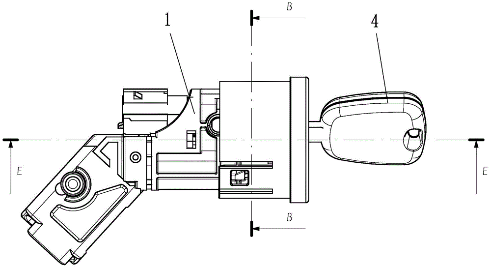
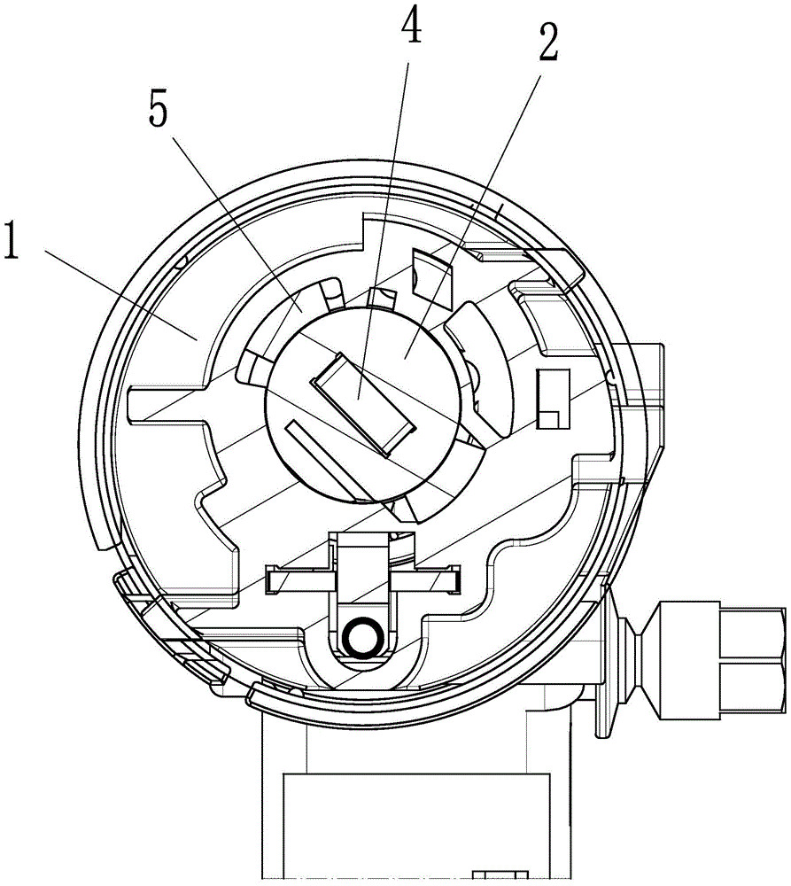
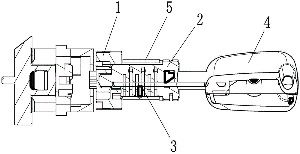
[0026] Embodiment 1: as figure 1 , 2 , Shown in 3, a kind of integrated anti-theft ignition switch for rental car, comprises lock body 1, the lock core 2 that is coaxially arranged with lock body, key 4 is inserted in the lock core, and lock plate 3 is arranged inside the lock core. A limit card is set on the outside of the lock cylinder, such as Figure 4 As shown, the section of the limit card is fan-shaped. The inner surface of the limit card is attached to the outer surface of the lock cylinder. The height of the limit card is the same as that of the lock cylinder. The position of the limit card is radially corresponding to the position of the lock plate. There are two limit cards, two limit cards The cards are evenly distributed around the axis of the lock cylinder.
[0027] The lock body is coaxially provided with a lock core, a lock plate is arranged in the lock core, and a limit card is arranged outside the lock core. The position of the limit card is radially corr...
Embodiment 2
[0028] Embodiment 2: The structure of this embodiment is basically the same as that of Embodiment 1, the difference is that, as Figure 5 , 8 As shown, the bottom of the limit card is provided with a chute parallel to the limit card, and the two ends of the chute are slidably connected with the top 6, and the pre-tension spring 7 for tightening the top is arranged in the chute, and the pre-tension spring is located at two between the heads. Such as Figure 6 As shown, the chute includes a limit groove 51 and a guide groove 52. The section of the chute is "T" shaped, the section of the limit groove is fan-shaped and the radian is the same as that of the limit card section, and the cross-sectional shape of the top is the same as that of the chute. And clearance fit. Such as Figure 7 As shown, one end of the plug located inside the chute is provided with a positioning post 61, and the pre-tightening spring is sleeved on the positioning post.
[0029]The bottom of the limit ...
Embodiment 3
[0030] Embodiment 3: The structure of this embodiment is basically the same as that of Embodiment 1 or 2, the difference is that, as Figure 9 As shown, a horizontal tongue 8 is provided at the bottom of the free end of the plug. When installing, press down the two plugs, place the limit card and the top on the outside of the lock cylinder, and after the top is released, the top protrudes toward both sides. The horizontal tongue can be inserted into the slots at both ends of the lock cylinder to realize the snap-fit connection of the limit card, avoid the separation of the limit card and the lock cylinder, and avoid the noise generated by the vibration of the limit card.
PUM
 Abstract
Description
Claims
Application Information
 - R&D
- Intellectual Property
- Life Sciences
- Materials
- Tech Scout
- Unparalleled Data Quality
- Higher Quality Content
- 60% Fewer Hallucinations
Browse by: Latest US Patents, China's latest patents, Technical Efficacy Thesaurus, Application Domain, Technology Topic, Popular Technical Reports.
© 2025 PatSnap. All rights reserved.Legal|Privacy policy|Modern Slavery Act Transparency Statement|Sitemap|About US| Contact US: help@patsnap.com


