
Chip blowing device for stamping die

A stamping die and stamping surface technology, which is applied in the field of auto parts processing devices, can solve the problems of manual injury and low efficiency, and achieve the effect of eliminating hazards and improving chip removal efficiency

Active Publication Date: 2016-01-06
上海金众汽车配件有限公司
View PDF7 Cites 8 Cited by
  • Summary
  • Abstract
  • Description
  • Claims
  • Application Information

AI Technical Summary

Problems solved by technology

However, this method of debris removal requires manual operation, which is inefficient, and the debris is also easy to cause damage to the operator's body

Method used


Image

  • Chip blowing device for stamping die
  • Chip blowing device for stamping die

Examples


Embodiment Construction

[0024] In order to make the technical means, creative features, objectives and effects achieved by the present invention easy to understand, the present invention will be further elaborated below.

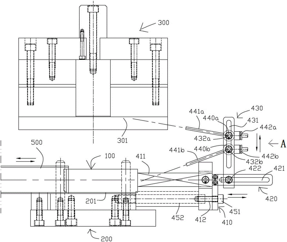
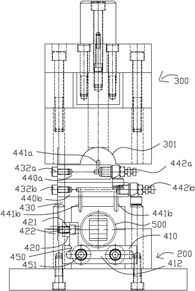
[0025] see figure 1 with figure 2 Shown is a chip blowing device for a stamping die, an upper die 300, a lower die 200, a mandrel 100 and a chip blowing device 400, the top of the upper die 300 is connected with a lifting drive device (not shown in the figure) to drive the upper die 300 lifting and moving, the mandrel 100 is arranged on the upper surface of the lower mold 200, and the chip blowing device 400 is arranged on the side of the mandrel 100 away from the entry end of the workpiece 500 (ie figure 1 The right side in, hereinafter referred to as this side is the right side of the mandrel 100).

[0026] The chip blowing device 400 includes a mandrel base 410 , a horizontal mounting frame 420 and a vertical mounting frame 430 . The mandrel seat 410 is arranged on the right...


PUM


Abstract

The invention discloses a chip blowing device for a stamping die. The stamping die comprises a lower die body, a mandrel arranged on the lower die body, an upper die body which can rise and fall, and the chip blowing device. The chip blowing device comprises a mandrel base, a horizontal installation frame, a vertical installation frame, an upper air pipe installation base and a lower air pipe installation base. The mandrel base is arranged on the side, away from the workpiece inlet end, of the mandrel and connected with the end, away from the workpiece inlet end, of the mandrel through a connecting arm. One end of the horizontal installation frame is fixed to the mandrel base. The vertical installation frame is installed on the horizontal installation frame. An upper high-pressure air blowing pipe is arranged on the upper air pipe installation base, and lower high-pressure air blowing pipes facing the stamping surface of the lower die body are arranged on the lower air pipe installation base. The upper high-pressure air blowing pipe and the lower high-pressure air blowing pipes are connected with a high-pressure air source through one-way control switches respectively. The one-way control switches are connected with a first travel switch arranged on the upper die body and a second travel switch arranged on one side of the workpiece inlet end of the mandrel. By the adoption of the chip blowing device, full-automatic chip removal of the stamping surface of the upper die body and the stamping surface of the lower die body is achieved.

Description

technical field [0001] The invention relates to a processing device for auto parts, in particular to a chip blowing device for a stamping die for tubular parts or cylindrical parts. Background technique [0002] The tubular parts or cylindrical parts of automobiles are mostly stamped and formed by stamping dies. The tubular parts or cylindrical parts are pre-fixed on the mandrel, and then stamped and formed by the upper and lower dies, and the unnecessary parts are removed by stamping. However, during the stamping and forming process of the mold, there will be debris on the stamping surfaces of the upper mold and the lower mold. If the debris is not removed in time, the quality of the next stamping and forming will be affected. [0003] The current way is that the stamped workpiece is withdrawn from the mandrel, and then the stamping surfaces of the upper mold and the lower mold are removed by manual hand-held air guns to remove the debris on the stamping surfaces of the upp...

Claims


Application Information

Patent Timeline
IPC IPC(8): B08B5/02B08B13/00
CPCB08B5/02B08B13/00
Inventor 陆华平
Owner 上海金众汽车配件有限公司
Learn More