Annular bidirectional stepping push rod chip removal device

A chip removal device, a step-by-step technology, applied to chip rolling, can solve the problem of low cleaning efficiency of iron chips, and achieve the effects of reducing labor intensity, low energy consumption, and wide application range

Active Publication Date: 2018-09-21
共享机床辅机(大连)有限公司
View PDF6 Cites 2 Cited by
  • Summary
  • Abstract
  • Description
  • Claims
  • Application Information

AI Technical Summary

Problems solved by technology

[0003] Aiming at the problem of low cleaning efficiency of iron filings generated when the gantry machine tool uses a rotary table to process large parts, the present invention invents an annular bidirectional stepping rod chip remover to collect and discharge iron filings in real time

Method used


Image

  • Annular bidirectional stepping push rod chip removal device
  • Annular bidirectional stepping push rod chip removal device
  • Annular bidirectional stepping push rod chip removal device

Examples


Embodiment Construction

[0019] The patent will be described in further detail below in conjunction with the accompanying drawings and specific embodiments.

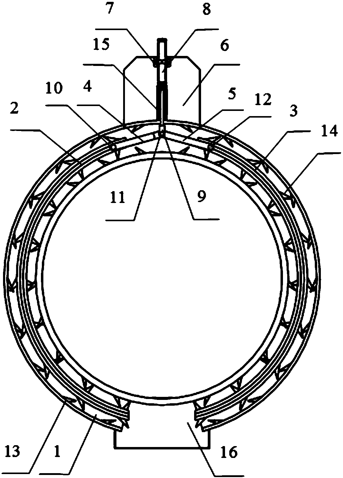
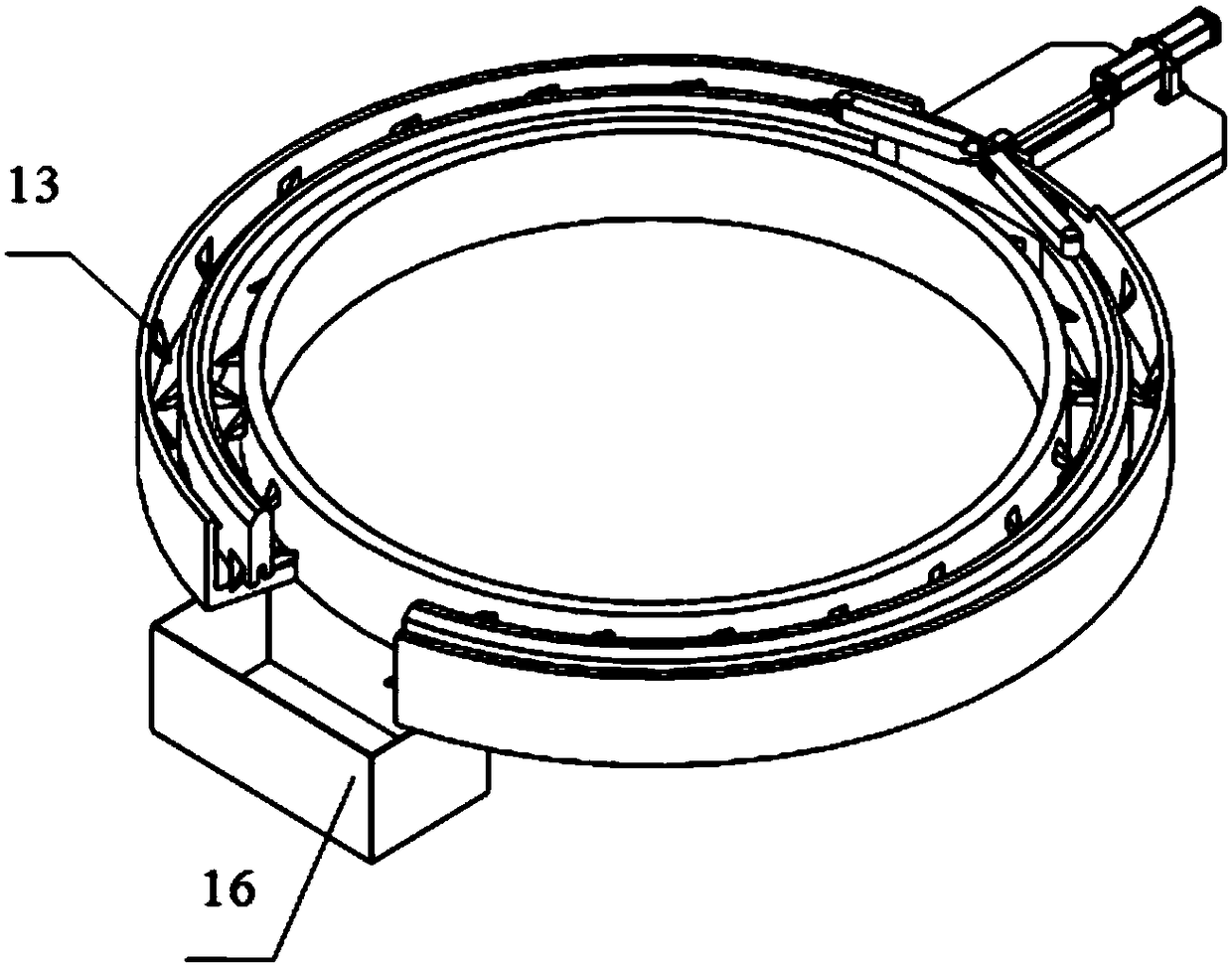
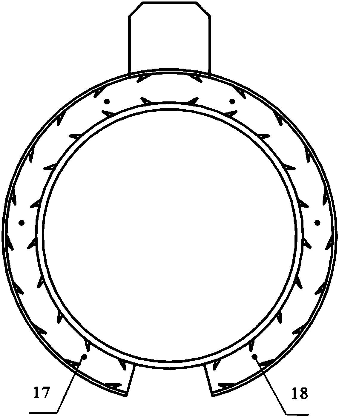
[0020] An annular two-way stepping push rod chip removal device mainly includes an annular groove body 1, an annular push rod 1 2, an annular push rod 2 3, a connecting rod 4, a connecting rod 2 5, a support plate 6, and a support 7. Oil cylinder 8, joint 9, pin one 10, pin two 11, pin three 12, chip retaining structure 13, chip pushing structure 14, guide groove 15, chip receiving bucket 16, guide roller one 17, guide roller two 18.

[0021] Wherein ring-shaped push rod one 2, ring-shaped push rod two 3, connecting rod one 4, connecting rod two 5 are located inside the annular groove body 1, and ring-shaped push rod one 2, ring-shaped push rod two 3, connecting rod one 4, The two ends of the connecting rod 5 have a through hole respectively, which is used to connect with relevant functional parts; one end of the annular tank body 1 is an open ...


PUM


Abstract

The invention provides an annular bidirectional stepping push rod chip removal device, and particularly relates to a device for removing lump chips, long chips and roll chips generated by working procedures such as turning, milling, drilling and boring when a gantry type machine tool is used for machining large parts. The annular bidirectional stepping push rod chip removal device mainly solves the problem of low cleaning efficiency of iron chips generated in machining of the large parts by a rotating table on the gantry type machine tool, and the iron chips can be immediately generated, collected and discharged. The annular bidirectional stepping push rod chip removal device has the advantages of wide applicable range, high chip removal efficiency, low energy consumption, stability, reliability, low cost and small occupied area, the use environment of a site can be effectively improved, and the labor intensity of staff is reduced.

Description

technical field [0001] The invention provides an annular two-way stepping rod chip removal device, in particular to a device for chip removal of lumpy chips, long chips, and rolling chips produced in the processes of turning, milling, drilling, and boring by using a gantry machine tool to process large parts. device. Background technique [0002] Gantry machine tools usually fix the workpiece on the rotary table and realize the processing of the workpiece through the rotation of the table. This processing method usually produces a large number of long chips and group chips in the processes of turning, milling, drilling, and boring. . Due to the rotation of the worktable, the iron filings are often entangled with each other and form a ball. This phenomenon is especially obvious in the processing of materials with good toughness, such as ordinary carbon steel and non-metallic materials. Usually, there are two ways to clean up the iron filings produced by this processing meth...

Claims


Application Information

Patent Timeline
Patent Type & Authority Applications(China)
IPC IPC(8): B23Q11/00
CPCB23Q11/0042
Inventor 赵亚宁何国峰马同堂何立军
Owner 共享机床辅机(大连)有限公司
Why Eureka
Try Eureka