Trash can clamping device

A technology for a clamping device and a trash can, which is applied in the directions of cleaning hollow objects, cleaning methods and utensils, chemical instruments and methods, etc., can solve the problems of small clamping surface, insufficient clamping, easy to be clamped, etc. Flip function, improve clamping stability, increase the effect of clamping stability

Active Publication Date: 2016-01-06
YANGZHOU JINWEI ENVIRONMENTAL PROTECTION TECH CO LTD
View PDF10 Cites 3 Cited by
  • Summary
  • Abstract
  • Description
  • Claims
  • Application Information

AI Technical Summary

Problems solved by technology

[0003] In the prior art, the trash can is clamped by the movable chuck and the fixed chuck, but the disadvantages of the prior art are revealed during use: one is that the clamping surface is relatively small, and the bucket edge at the opening of the trash can is outward. The roll mouth structure, and the upper opening end of the trash can is a rectangular structure, only one side is clamped during use, making the clamping not firm enough; second, the clamping process of the trash can is like the moving chuck and the fixed chuck biting each other. Hold the side of the trash can, and the moving chuck is directly driven by the cylinder, because the side of the barrel is a rolled mouth structure, it is easy to be clamped

Method used


Image

  • Trash can clamping device
  • Trash can clamping device
  • Trash can clamping device

Examples


Embodiment Construction

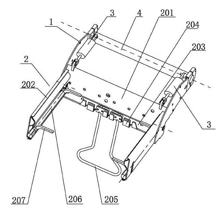
[0016] Such as Figure 1-5 As shown, a trash can clamping device includes a bracket 1 whose feet are fixedly set on the turning shaft 4, and also includes a turning frame 2 rotatably mounted on the head of the bracket 1, a turning cylinder 3, and a turning cylinder 3 The piston rod is hinged with the overturn frame 2, and the cylinder barrel of the overturn cylinder 3 is hinged with the support 1 foot.

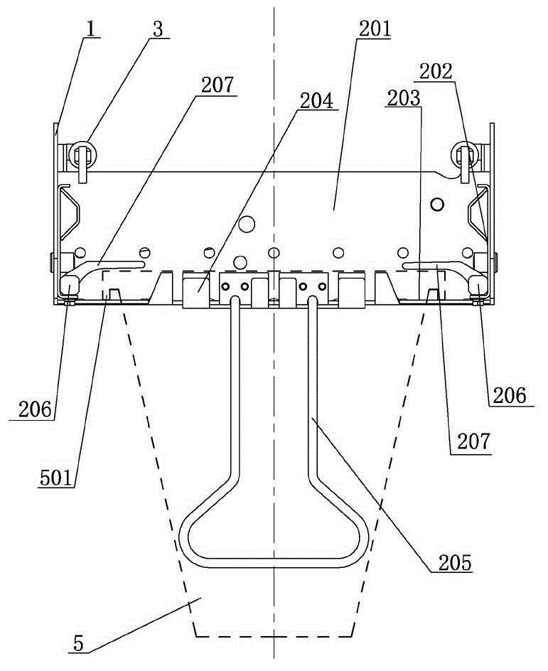
[0017] The above-mentioned overturning frame 2 includes a front baffle 201 extending parallel to the overturning axis 4, and both ends of the front baffle 201 are provided with side baffles extending perpendicular to the overturning axis 4 and located on the clamping side of the front baffle 201. plate 202.

[0018] The lower end of the clamping side of the front baffle 201 is provided with a support platform 203 for supporting the barrel edge 501 , and the support platform 203 is provided with a limiting plate 204 for hooking the barrel edge 501 .

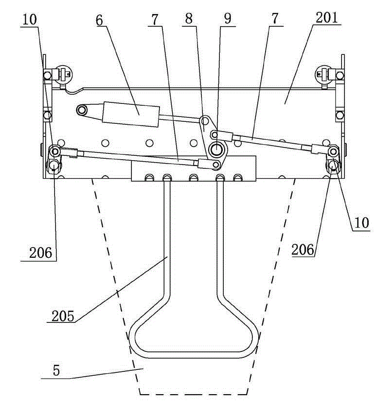
[0019] The lower side of...


PUM


Abstract

The invention discloses a trash can clamping device, and belongs to the technical field of environmental sanitary equipment. The trash can clamping device comprises a support, and further comprises an overturn frame and an overturn air cylinder. A piston rod of the overturn air cylinder is hinged to the overturn frame. A cylinder barrel of the overturn air cylinder is hinged to the foot of the support. The overturn frame comprises a front baffle. Side baffles are arranged at the two ends of the front baffle respectively. A supporting table is arranged at the lower end of the clamping side of the front baffle and provided with a limiting plate used for hooking the can edge. The two side baffles are provided with can pressing mechanisms. The front baffle is provided with a compression driving mechanism. Each can pressing mechanism comprises a first rotating shaft, wherein the first rotating shaft is installed on the overturn frame in a rotatable manner, and the power input end of the first rotating shaft penetrates the front baffle and is located on the non-clamping side of the front baffle. The clamping section of each first rotating shaft is at least fixedly provided with two pressing blocks. When the trash can clamping device is used, the first rotating shafts are controlled by the compression driving mechanism to rotate to the compression position, and the pressing blocks press the opening end on the upper portion of a trash can; and accordingly, the clamping stability can be ensured, and the edge of the trash can further can be prevented from being damaged by clmaping.

Description

technical field [0001] The invention relates to the technical field of sanitation equipment, in particular to a trash can clamping device used on a trash can cleaning vehicle. Background technique [0002] In the prior art, a fully automatic environmental protection collection box high-pressure cleaner is disclosed, the application number is 201010539700.X, the application date is November 11, 2010, and the patentee is Hywell Machinery (Yangzhou) Co., Ltd. In this patent, the overturning clamping mechanism plays an important role, including two parts, the overturning shaft and the clamping mechanism for clamping the trash can, wherein the overturning shaft is controlled by the overturning motor, and the trash can is clamped by the clamping mechanism Finally, start the flipping motor, the flipping shaft rotates, and the clamping mechanism flips the trash can to the cleaning position. Therefore, the clamping mechanism needs to clamp the trash can firmly. [0003] In the prio...

Claims


Application Information

Patent Timeline
Patent Type & Authority Applications(China)
IPC IPC(8): B08B9/28
Inventor 陈彪
Owner YANGZHOU JINWEI ENVIRONMENTAL PROTECTION TECH CO LTD
Why Eureka
Try Eureka