Rear cross beam of vehicle and vehicle

A technology for rear beams and vehicles, which is applied to vehicle components, transportation and packaging, and substructures. It can solve the problems that straight-tube beams cannot meet the space requirements of motors and there is not enough straight-tube beams, and achieve reasonable space distribution and layout. compact effect

Active Publication Date: 2016-01-06
BEIJING ELECTRIC VEHICLE
View PDF6 Cites 1 Cited by
  • Summary
  • Abstract
  • Description
  • Claims
  • Application Information

AI Technical Summary

Problems solved by technology

[0002] Most of the rear beams of existing vehicles use straight-tube beams, but for rear-drive vehicles or other vehicles with vertical motors, the inventors found that straight-tube beams cannot meet the space requirements fo

Method used


Image

  • Rear cross beam of vehicle and vehicle
  • Rear cross beam of vehicle and vehicle
  • Rear cross beam of vehicle and vehicle

Examples


Embodiment Construction

[0034] Embodiments of the present invention are described in detail below, examples of which are shown in the drawings, wherein the same or similar reference numerals designate the same or similar elements or elements having the same or similar functions throughout. The embodiments described below by referring to the figures are exemplary and are intended to explain the present invention and should not be construed as limiting the present invention.

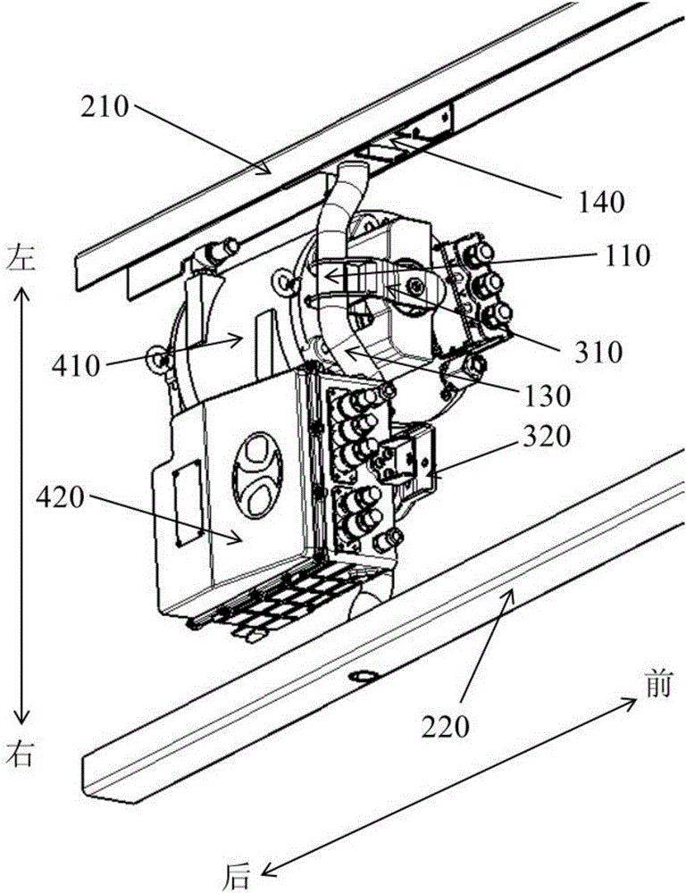
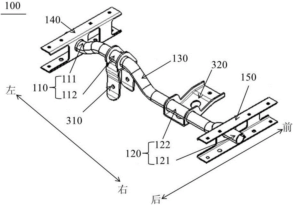
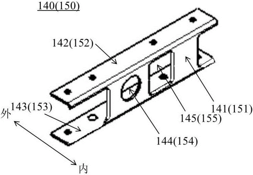
[0035] In describing the present invention, it should be understood that the terms "length", "width", "thickness", "upper", "lower", "front", "rear", "left", "right", " The orientations or positional relationships indicated by "vertical", "horizontal", "top", "bottom", "inner" and "outer" are based on the orientations or positional relationships shown in the drawings, and are only for the convenience of describing the present invention and Simplified descriptions, rather than indicating or implying that the device or element refe...


PUM


Abstract

The invention discloses a rear cross beam of a vehicle and the vehicle. The rear cross beam of the vehicle comprises a first section and a second section. The left end of the first section is suitable for being connected with a left longitudinal beam of the vehicle. The right end of the second section is suitable for being connected with a right longitudinal beam of the vehicle. The right end of the first section is connected with the left end of the second section. The height, in the vertical direction, of at least part of the first section is larger or smaller than that, in the vertical direction, of at least part of the second section. According to the rear cross beam of the vehicle, space near the rear cross beam is more reasonably distributed, other parts are suitable for being installed in the space, and the layout requirements of a power system or other parts of the rear-drive type vehicle can be met.

Description

technical field [0001] The invention belongs to the technical field of vehicle manufacturing, and in particular relates to a rear beam of a vehicle and a vehicle with the rear beam. Background technique [0002] Most of the rear beams of existing vehicles use straight-tube beams, but for rear-drive vehicles or other vehicles with vertical motors, the inventors found that straight-tube beams cannot meet the space requirements for motor layout, and the motors are installed in straight tubes. The vertical beam is too close to the ground, and there is not enough space above the straight beam for arranging other related parts, so there is room for improvement. Contents of the invention [0003] The present invention aims to solve one of the technical problems in the related art at least to a certain extent. For this reason, it is an object of the present invention to propose a rear cross member of a vehicle with a rational spatial distribution. [0004] Another object of the ...

Claims


Application Information

Patent Timeline
IPC IPC(8): B62D21/02B62D21/09
Inventor 叶伟高占恒高敏王立堂李力华马博
Owner BEIJING ELECTRIC VEHICLE
Why Eureka
Try Eureka