
Electric meter box

A technology of electric meter box and flat panel, which is applied in the field of electric meter box, can solve the problems of increased volume of electric meter box, inconvenient installation and production, difficulty in reading and maintenance of electric energy meter, etc., and achieve reasonable space distribution, convenient installation and maintenance, and reduced volume Effect

Inactive Publication Date: 2022-01-04
韩景忠
View PDF0 Cites 0 Cited by
  • Summary
  • Abstract
  • Description
  • Claims
  • Application Information

AI Technical Summary

Problems solved by technology

[0002] The electric energy meter box is the basis for the standard installation of electric energy metering devices. At present, because each household needs to install at least one electric energy meter, and the number of users is large, the consumption of electric energy meter boxes is also increasing. In the prior art, due to the use of electric energy meters The volume of the meter box is getting bigger and bigger, which makes the volume of the meter box also increase, which causes a lot of inconvenience to its installation and production; and in real life, for the sake of safety and to avoid unnecessary bumps, the meter box is generally installed on a high However, this installation will cause many difficulties for the staff to read and maintain the energy meter

Method used


Image

  • Electric meter box
  • Electric meter box
  • Electric meter box

Examples


Embodiment Construction

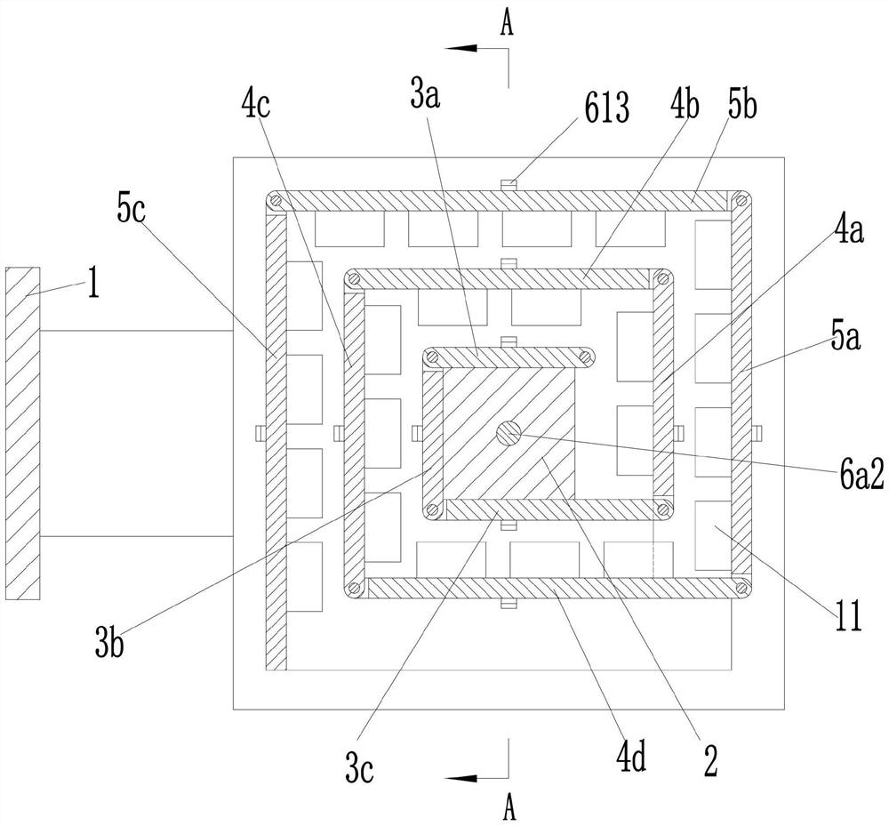
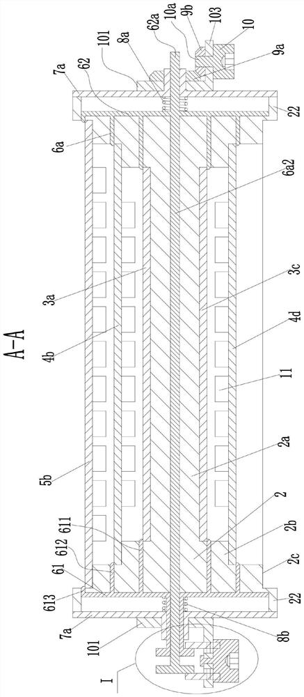
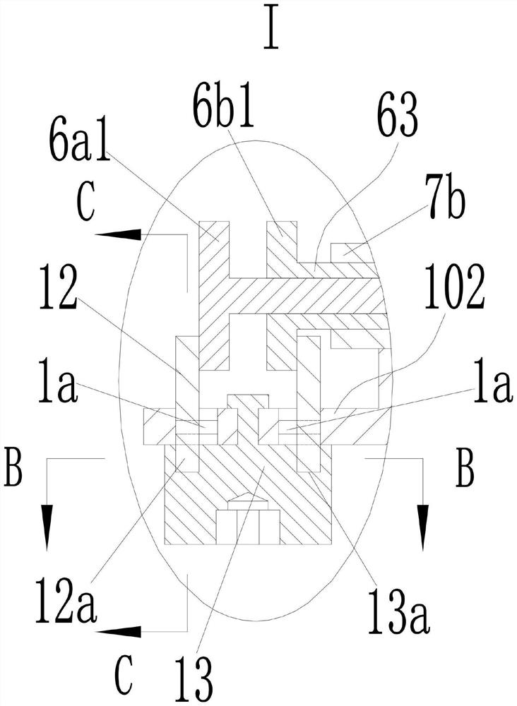
[0026] see Figure 1-9 As shown, a meter box includes a mounting frame 1, lugs 101 are provided on the left and right sides of the mounting frame 1, each lug 101 is rotatably connected with a first shaft sleeve 21, and two first shafts The sleeves 21 are in the coaxial position, the opposite ends of the two first shaft sleeves 21 are provided with square end caps 7a, and the end faces of the two end caps 7a are fixed with bases 22, and the two bases 22 are The first square bosses 2c are fixed on the opposite end faces, the second square bosses 2b are arranged on the opposite end faces of the two first square bosses 2c, and the opposite end faces of the two second square bosses 2b A third square boss 2a is arranged therebetween, and the surrounding sides of the third square boss 2a are parallel to the surrounding sides of the second square boss 2b, and the surrounding sides of the second square boss 2b are parallel to the sides of the first square boss 2c. The surrounding side...


PUM


Abstract

The invention discloses an electric meter box comprising a mounting rack, the left side and the right side of the mounting rack are both provided with convex lugs, a first shaft sleeve is rotatably connected in each convex lug, the opposite ends of the two first shaft sleeves are both provided with end covers, the opposite end surfaces of the two end covers are both fixedly provided with bases, and the opposite end surfaces of the two bases are both fixedly provided with first square convex columns. Second square convex columns are arranged on the opposite end faces of the two first square convex columns, and a third square convex column is arranged between the opposite end faces of the two second square convex columns; a connecting plate assembly is hinged between the opposite end faces of the two second square convex columns, a first mounting plate assembly is hinged to the connecting plate assembly, a second mounting plate assembly is hinged to the first mounting plate assembly, and the first mounting plate assembly and the second mounting plate assembly are used for mounting electricity meters; the electric meter box further comprises a positioning assembly. A knob assembly and a driving assembly are arranged on a mounting frame; the electric meter box is simple in structure, small in size and convenient to operate and use.

Description

technical field [0001] The invention belongs to the technical field of electrical components, and in particular relates to an electric meter box. Background technique [0002] The electric energy meter box is the basis for the standard installation of electric energy metering devices. At present, because each household needs to install at least one electric energy meter, and the number of users is large, the consumption of electric energy meter boxes is also increasing. In the prior art, due to the use of electric energy meters The volume of the meter box is getting bigger and bigger, which makes the volume of the meter box also increase, which causes a lot of inconvenience to its installation and production; and in real life, for the sake of safety and to avoid unnecessary bumps, the meter box is generally installed on a high However, this installation will cause many difficulties for the staff to read and maintain the energy meter. Contents of the invention [0003] The...

Claims


Application Information

Patent Timeline
Patent Type & Authority Applications(China)
IPC IPC(8): G01R11/04
CPCG01R11/04
Inventor 韩景忠林成东张和志
Owner 韩景忠
Learn More