
Cast-in-place reinforced concrete independent beam support device

A technology of reinforced concrete and supporting devices, applied in the direction of pillars, joists, girders, etc., can solve problems such as calculation discrepancies, safety accidents, and unbalanced force on two vertical columns

Inactive Publication Date: 2016-01-06
HEBEI ZHONGJIAN ENG CO LTD
View PDF5 Cites 0 Cited by
  • Summary
  • Abstract
  • Description
  • Claims
  • Application Information

AI Technical Summary

Problems solved by technology

[0005] The purpose of the present invention is to provide a cast-in-place reinforced concrete independent beam support device to solve the unbalanced force of the two vertical columns in the prior art, so that the actual situation of erection does not match the calculation of the elevated body support system, which may cause The support device collapsed, causing serious quality accidents and technical problems in safety accidents

Method used


Image

  • Cast-in-place reinforced concrete independent beam support device
  • Cast-in-place reinforced concrete independent beam support device

Examples


Embodiment 1

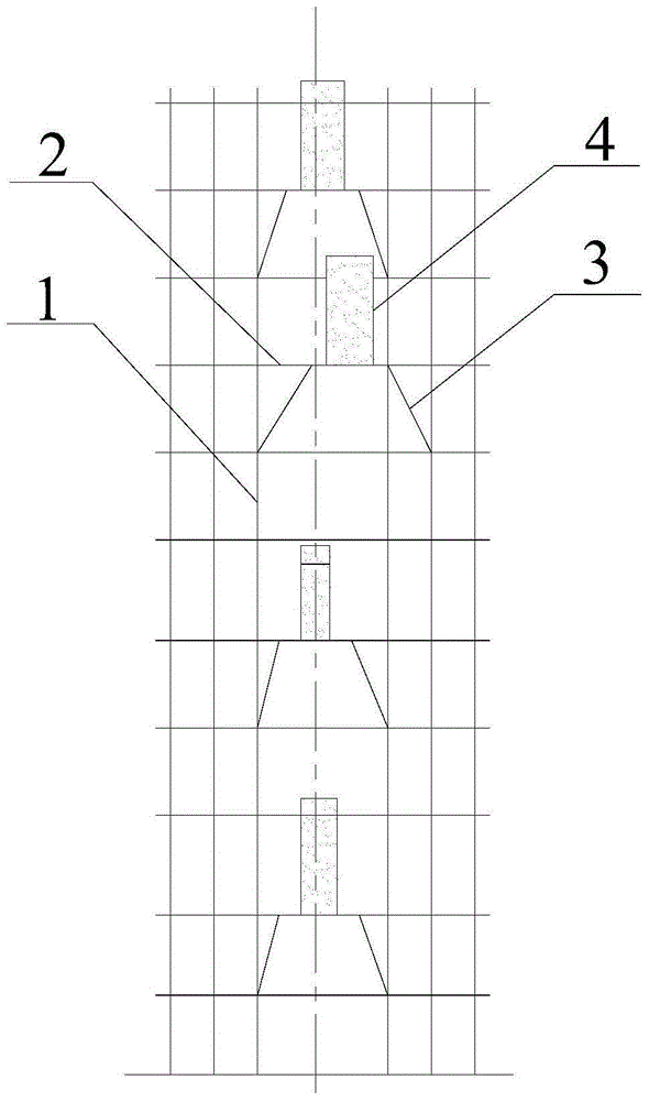
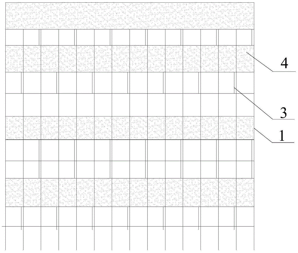
[0039] figure 1 A side view of a cast-in-place reinforced concrete independent beam support device provided in an embodiment of the present invention; figure 2 A front view of a cast-in-place reinforced concrete independent beam support device provided in an embodiment of the present invention; as figure 1 and figure 2As shown, a cast-in-place reinforced concrete independent beam support device provided in this embodiment includes an integral support device, and the overall support device includes two rows of vertical columns 1 parallel to each other, and a plurality of cast-in-place reinforced concrete independent beams 4 of different heights. Set between two rows of vertical columns 1, each set of opposite rows of vertical columns 1 is provided with a plurality of horizontal horizontal bars 2 parallel to each other, and cast-in-place reinforced concrete independent beams 4 are set on some of the horizontal horizontal bars 2 ;

[0040] Auxiliary support devices are conne...

Embodiment 2

[0044] figure 1 A side view of a cast-in-place reinforced concrete independent beam support device provided in an embodiment of the present invention; figure 2 A front view of a cast-in-place reinforced concrete independent beam support device provided in an embodiment of the present invention; as figure 1 and figure 2 As shown, a cast-in-place reinforced concrete independent beam support device provided in this embodiment includes an integral support device, and the overall support device includes two rows of vertical columns 1 parallel to each other, and a plurality of cast-in-place reinforced concrete independent beams 4 of different heights. Set between two rows of vertical columns 1, each set of two opposite vertical columns 1 is provided with a plurality of horizontal horizontal bars 2 parallel to each other, and cast-in-place reinforced concrete independent beams 4 are set on some of the horizontal horizontal bars 2 ;

[0045] Auxiliary support devices are connecte...


PUM


Abstract

The invention provides a cast-in-place reinforced concrete independent beam support device, which comprises an integral support device, wherein the integral support device comprises two rows of mutually parallel vertical upright posts; a plurality of cast-in-place reinforced concrete independent beams at different heights are arranged between the two rows of vertical upright posts; a plurality of mutually parallel transverse horizontal rods are arranged between each group of two opposite rows of vertical upright posts; the cast-in-place reinforced concrete independent beams are arranged on a part of the transverse horizontal rods; an auxiliary support device comprises two auxiliary support rods; and the two auxiliary support rods are arranged at two sides of the cast-in-place reinforced concrete independent beams and are in splayed arrangement. The cast-in-place reinforced concrete independent beam support device provided by the invention has the advantages that by using the cast-in-place reinforced concrete independent beam support device , the stress between the two vertical upright posts is balanced, so that the building of the cast-in-place reinforced concrete independent beam support device is safe and reliable; economical performance and practicability are realized; the occurrence of quality and safety accidents is avoided; the protection at the outer side of a frame body is convenient; and the appearance effect of the frame body is nice.

Description

technical field [0001] The invention relates to the technical field of building construction, in particular to a support device for cast-in-place reinforced concrete independent beams. Background technique [0002] Cast-in-place reinforced concrete independent beams belong to a construction method in building construction. During the construction process, at the same vertical position, there may be multiple cast-in-place reinforced concrete independent beams of different elevations. A corresponding support system is required. Although multiple cast-in-place reinforced concrete independent beams are in the same vertical position, they may not be in the same longitudinal section. [0003] At present, there are two commonly used support methods, one is to set up a separate support device for each cast-in-place reinforced concrete independent beam, that is, each cast-in-place reinforced concrete independent beam is provided with a separate support frame to achieve independent su...

Claims


Application Information

Patent Timeline
Patent Type & Authority Applications(China)
IPC IPC(8): E04C3/20E04G25/00
Inventor 张作亭李占成张玉龙许晓亮
Owner HEBEI ZHONGJIAN ENG CO LTD
Learn More