
Component of rolling-element bearing and method for manufacturing the same

A technology for rolling bearings and rolling elements, which is applied in the direction of rolling contact bearings, roller bearings, rotating bearings, etc., and can solve problems such as shortened service life of bearings

Inactive Publication Date: 2016-01-06
AB SKF
View PDF5 Cites 0 Cited by
  • Summary
  • Abstract
  • Description
  • Claims
  • Application Information

AI Technical Summary

Problems solved by technology

As a result, this higher friction and / or higher wear can sometimes lead to reduced bearing service life

Method used


Image

  • Component of rolling-element bearing and method for manufacturing the same
  • Component of rolling-element bearing and method for manufacturing the same
  • Component of rolling-element bearing and method for manufacturing the same

Examples


Embodiment Construction

[0029] In the following description of the drawings, the same reference numerals denote the same or similar components. Furthermore, summative reference signs are used for those parts and objects that appear several times in the exemplary embodiments or in the drawings, but are generally described with respect to one or more features thereof. Components or objects denoted with the same or collective reference signs can be implemented identically with regard to single, multiple or all technical features, for example with respect to their dimensions, but can also be implemented differently, as long as it is not clear from the description Get different express or implied.

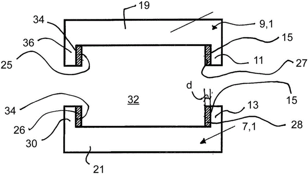
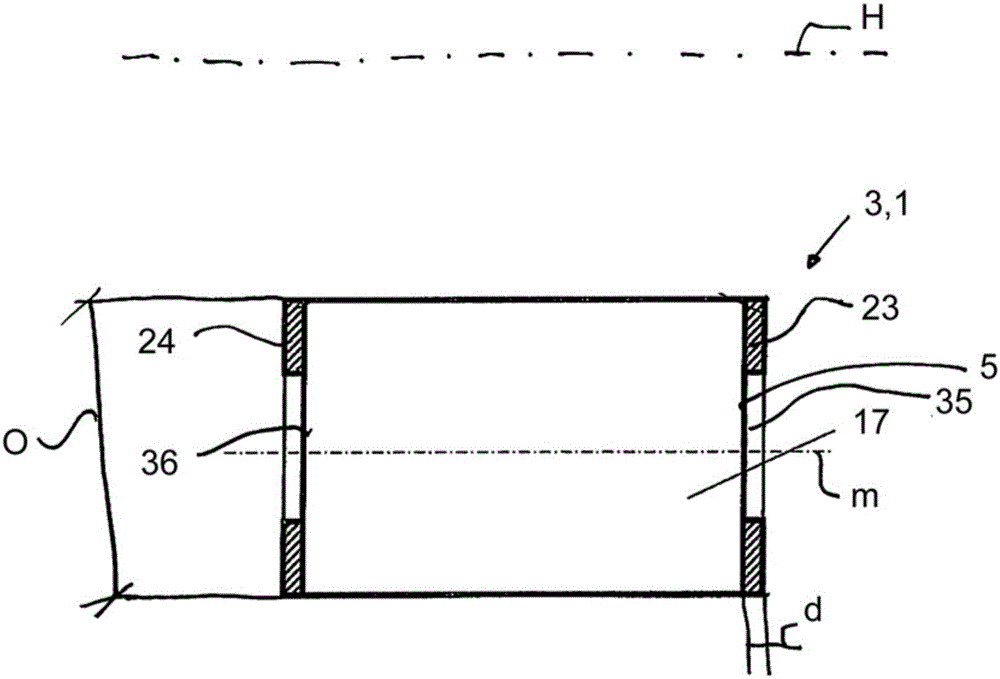
[0030] figure 1 A schematic diagram showing a cross-section of an outer ring and an inner ring as a device for a rolling bearing according to an exemplary embodiment of the invention.

[0031] figure 1 A device 1 for rolling bearings is shown. A rolling bearing comprises at least one rolling element 3, for...


PUM

PropertyMeasurementUnit
thicknessaaaaaaaaaa
lengthaaaaaaaaaa

Abstract

A component of a rolling-element bearing, such as a bearing inner ring having an inner ring flange, a bearing outer ring having an outer ring flange or a rolling element having an end surface, includes a solid slide layer having a lower coefficient of friction than a material to which the slide layer is attached which slide layer reduces frictional contact between the component and another component against which the slide layer slides during bearing operation.

Description

technical field [0001] The invention relates to a device for a rolling bearing and a method for producing a device for a rolling bearing. Background technique [0002] In rolling bearings (for example cylindrical roller bearings (CRB), tapered roller bearings (TRB)) axial stresses can develop such that the rolling bearings press against the inside of the rib (guide rib). Therefore, sometimes there may be a relatively high axial pressing force acting on the inner side of the rib and the end surface of the rolling element. In addition, sliding friction contact or sliding friction may sometimes occur between the rolling elements and the rib. Sometimes a sliding frictional contact between two parts, for example two parts made of steel, can lead to higher wear of the parts and / or higher friction between the parts. [0003] Higher friction in this area, for example between the end faces of the rolling elements and the guide rib, can also lead, for example, to higher energy consu...

Claims


Application Information

Patent Timeline
Patent Type & Authority Applications(China)
IPC IPC(8): F16C33/58F16C33/62
CPCF16C2240/60F16C2223/32F16C33/34F16C33/585F16C33/62F16C33/64F16C2208/82F16C19/26F16C19/225
Inventor T.克劳斯
Owner AB SKF
Learn More