Floating vessel for servicing air diffusers

a technology for air diffusers and floating vessels, which is applied in the field of floating vessels, can solve the problems of unstable and uneven work platforms for workers, extreme unsafe methods of working on submerged diffusers, etc., and achieve the effect of increasing friction characteristics and offering further stability to the vessel

Inactive Publication Date: 2011-09-29
ESCHER FRED FRANCIS
View PDF5 Cites 10 Cited by
  • Summary
  • Abstract
  • Description
  • Claims
  • Application Information

AI Technical Summary

Benefits of technology

[0007]It is another object of the invention to provide a lifting barge that can safely accommodate the servicing personnel during the air diffusers maintenance.
[0008]It is another object of the invention to provide a lifting barge that can retain the air diffuser assembly within easy reach of the service personnel on the barge.
[0011]A lifting assembly is secured on the cross header such that the lifting assembly extends above the space between the two pontoons. A railing assembly is secured to the frame assembly and mounted on the upper deck of each of the pontoons. The railing assembly comprises a support plate, which extends along an inner edge of the pontoon and is configured for supporting an air diffuser during servicing. A top surface of the support plate is formed with increased friction characteristics to help retain a wet air diffuser on the vessel during servicing.
[0012]A railing assembly is mounted on the upper decks of each pontoon to form an enclosed area and prevent small objects from sliding off the decks during the vessel operation. A handrail is connected to deck-mounted rails for safety. In one aspect of the invention, the railing assembly is secured to the frame assembly, thus offering further stability to the vessel.

Problems solved by technology

This was an extremely unsafe method of working on the submerged diffusers and most workers declined to do this work.
When in operation, the boat tilts forward from the weight of the air header, causing an unstable and uneven work platform for the workers.
Also, due to the method of operation and its round pontoons with flat ends, which do not move through the water easily, it needs a large outboard motor to maneuver in the basin.

Method used


Image

  • Floating vessel for servicing air diffusers
  • Floating vessel for servicing air diffusers
  • Floating vessel for servicing air diffusers

Examples


Embodiment Construction

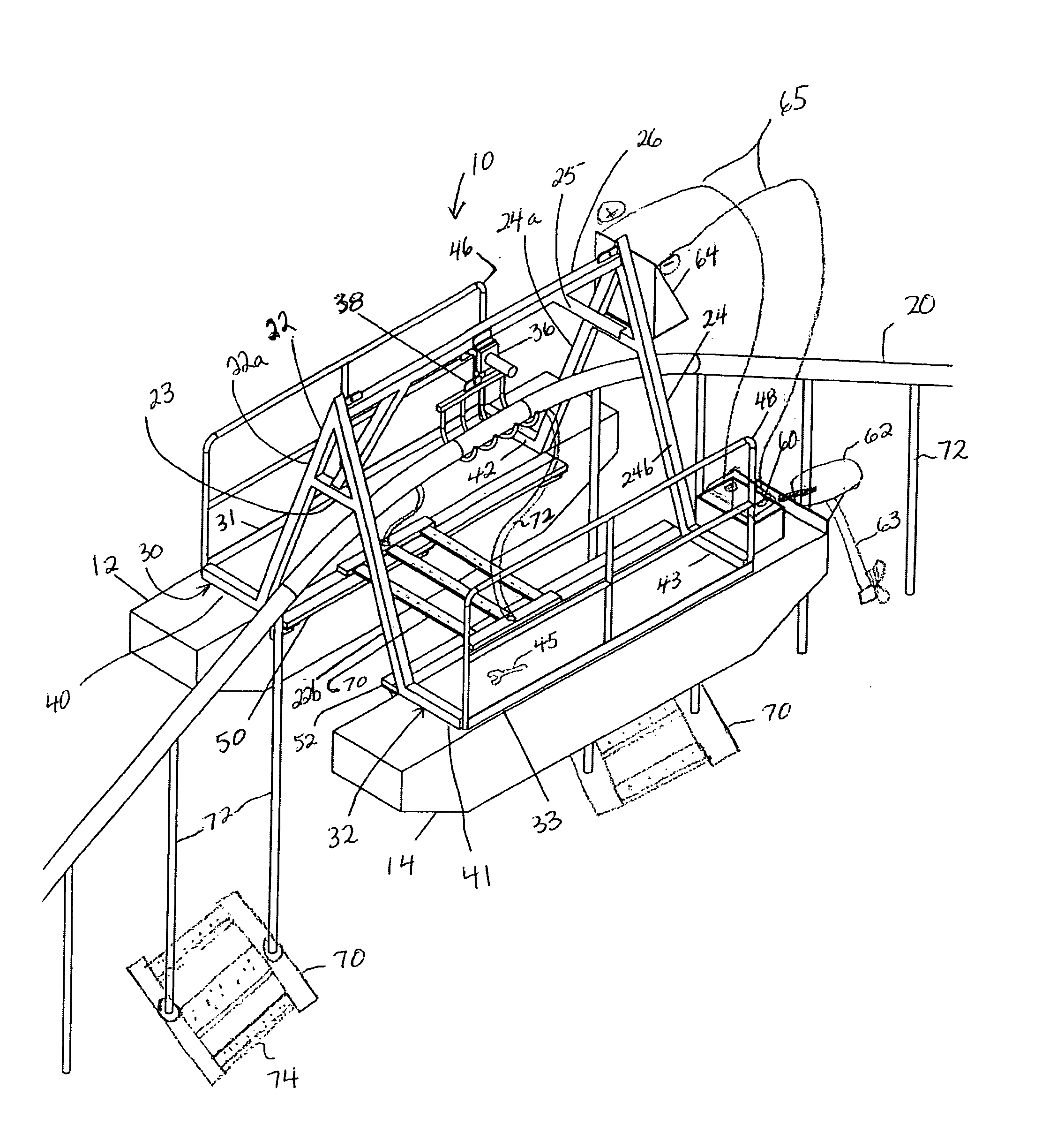
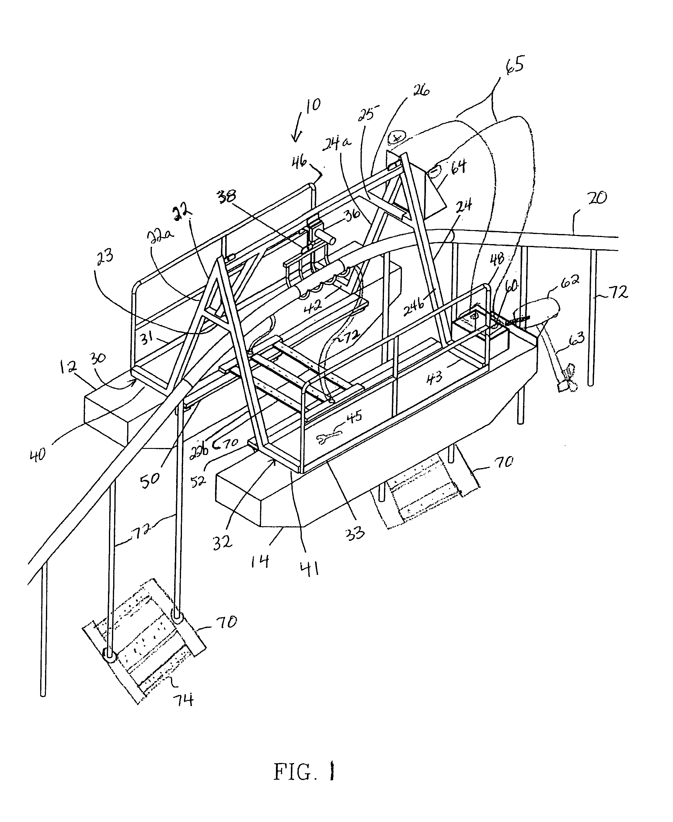
[0017]Turning now to the drawings in more detail, numeral 10 designates the floating vessel according to the present invention. The vessel 10 has a generally catamaran-type structure. The vessel 10 comprises a pair of spaced apart buoyant hulls 12 and 14. The hulls 12, 14 can be barges or any other buoyant bodies. The hulls 12 and 14 can be elongated pontoons having a generally square cross section in the center and slope-ended forward and aft portions. The pontoons 12 and 14 (sloped for ease of movement in the wastewater) can be constructed of ⅛″ thick aluminum plate but could also be constructed of a thicker plate if so desired for added strength and longevity.

[0018]A frame assembly 16 spans between the hulls 12, 14. The frame 16 extends upwardly in a generally A-shape that provides space under the frame and in between the hulls for enabling air diffusers to be positioned in between the hulls and under the frame 16. The space in between the hulls 12, 14 and under the frame 16 can ...


PUM


Abstract

A catamaran type vessel for use in a wastewater facility for servicing submerged air diffusers is disclosed. The vessel has spaced apart pontoon having an A-frame spanning between the upper decks of the pontoon and connecting the pontoons. A hook connected to a winch is secured to a cross header above the space between the pontoons. The hook is lowered into water and lifts an air header, to which the air diffusers are connected. An air diffuser is then pulled on the pontoons and serviced. The vessel is then propelled to a position to service other air diffusers in the pontoon.

Description

CROSS-REFERENCE TO RELATED APPLICATIONS[0001]This application is a continuation-in-part application which claims the benefit of provisional patent application Ser. No. 61 / 128,250, filed 2008 May 20 and co-pending nonprovisional application Ser. No. 12 / 454,525 filed on May 19, 2009 entitled “Barge for servicing air diffusers in wastewater plants,” the full disclosures of which are incorporated by reference herein and priority of which is hereby claimed.BACKGROUND OF THE INVENTION[0002]This invention relates to a floating vessel, specifically to an improved lifting barge adapted for servicing and maintaining submerged air diffusers in wastewater treatment facilities.[0003]In the past, the only equipment a wastewater treatment facility used, to maintain and service submerged diffusers, was a flat boat. Three (3) men were needed to accomplish this task. Two (2) men would manually lift the air header and lay it on the boat while the third man would sit across from them steadying the boat...

Claims


Application Information

Patent Timeline
Patent Type & Authority Applications(United States)
IPC IPC(8): B63B35/00B63B1/12B63B35/28B65G67/60B63B27/08B63B27/16
CPCB63B1/121B63B35/28B63B35/00B63B27/12B63B15/00B63B35/44B63H21/17
Inventor ESCHER, FRED FRANCIS
Owner ESCHER FRED FRANCIS
Why Eureka
Try Eureka