Humidifier water tank and humidifier with humidifier water tank

A technology for humidifiers and water tanks, applied in air humidification systems, heating methods, household appliances, etc., can solve the problems of complex water tank space, difficulty in mold release, etc., and achieve the effect of increasing the amount of humidification

Inactive Publication Date: 2016-01-06
GREE ELECTRIC APPLIANCES INC
View PDF21 Cites 3 Cited by
  • Summary
  • Abstract
  • Description
  • Claims
  • Application Information

AI Technical Summary

Benefits of technology

This new design solves problems with existing designs for making large spaces inside an atomizer' s liquid reservoir because it requires separate components such as the top cover or mistoutlet tubes from each other which makes up about 30% more space than what was previously needed. Additionally, this design allows for independent control over how much moisture content needs to reach certain points within the system without requiring excessive force on the part being used. Overall, these technical improvements improve performance and efficiency while reducing costs associated therewith

Problems solved by technology

Technological Problem addressed in this patented technical problem relates how to improve the efficiency and effectiveness of humidiators used at home without compromising their ability to maintain proper function when they use them over time.

Method used


Image

  • Humidifier water tank and humidifier with humidifier water tank
  • Humidifier water tank and humidifier with humidifier water tank
  • Humidifier water tank and humidifier with humidifier water tank

Examples


Embodiment Construction

[0034] Preferred embodiments of the present invention are described below, and it should be understood that the preferred embodiments described here are only used to illustrate and explain the present invention, and are not intended to limit the present invention.

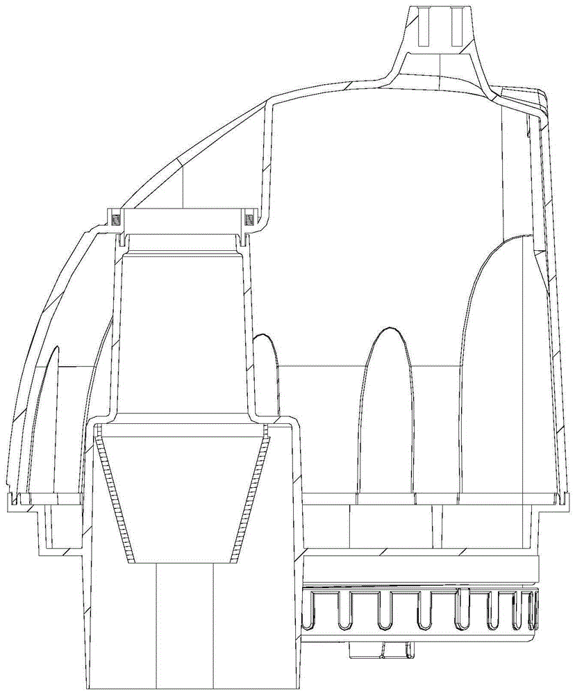
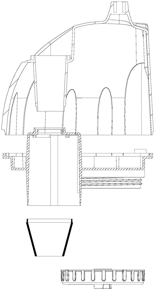
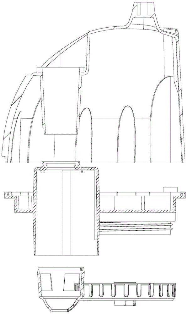
[0035] like Figure 1-3 As shown in , it shows a typical structural schematic diagram of humidifier water tanks commonly used in the market at present, and these water tanks all use non-detachable mist outlet pipe structures. in, Figure 1-2 The mist outlet pipe of the humidifier water tank is integrally formed with the bottom cover of the water tank. image 3 The mist outlet pipe of the humidifier water tank is integrally formed with the water tank shell. Water tanks using these types of mist outlet pipes generally have the problems of difficult mold release as mentioned above, the size of the mist outlet pipe is limited by the space size and molding process, and it is also prone to problems due to the installat...


PUM


Abstract

The invention discloses a humidifier water tank. The humidifier water tank comprises a water tank outer shell, a water tank bottom cover and a mist outlet pipe; the water tank outer shell and the water tank bottom cover are in butt joint to form a water storage space; the mist outlet pipe is located in the water storage space and is an independent component; the two ends of the mist outlet pipe are connected with the water tank outer shell and the water tank bottom cover in a sealed mode respectively. The mist outlet pipe is designed to be the independent component, so that the water tank outer shell, the water tank bottom cover and the mist outlet pipe are independently manufactured and removed from moulds, and then the problem that demoulding is difficult as a water tank is complex and the space is small is solved.

Description


Claims


Application Information

Patent Timeline
Owner GREE ELECTRIC APPLIANCES INC
Why Eureka
Try Eureka