
Delayed reverse inclined ejection mold stripping structure and mold stripping method

A lifter and lifter seat technology is applied in the field of delayed reverse lifter ejection structure and ejection, which can solve the problem that the ejection structure cannot be used for ejecting complex products.

Active Publication Date: 2021-09-10
SHANGHAI TIANHAI ELECTRONICS
View PDF5 Cites 0 Cited by
  • Summary
  • Abstract
  • Description
  • Claims
  • Application Information

AI Technical Summary

Problems solved by technology

[0006] The technical problem to be solved by the present invention is: the existing mold ejection structure cannot be applied to the mold ejection of complex products blocked by glue positions

Method used


Image

  • Delayed reverse inclined ejection mold stripping structure and mold stripping method
  • Delayed reverse inclined ejection mold stripping structure and mold stripping method
  • Delayed reverse inclined ejection mold stripping structure and mold stripping method

Examples


Embodiment Construction

[0032] In order to make the present invention more comprehensible, preferred embodiments are described in detail below with accompanying drawings.

[0033] The delayed reverse inclined ejection structure of the present invention adopts the structure of straight ejector and inclined ejector, and utilizes the plasticity of the product to allow the product to be deformed in the mold and then ejected. Delayed reverse inclined ejection structure includes straight top 1, inclined top 2 and inclined top seat 5, the top of straight top 1 is processed with straight top block 6, the bottom surface of straight top block 6 is connected with the end surface of straight top 1, straight top block The bottom surface of 6 is larger than the end surface area of ​​straight top 1, and the bottom surface of straight top block 6 and straight top 1 are L-shaped in the present embodiment.

[0034] like Figure 8 As shown, the chute 7 is processed on the inclined top seat 5, and the inside of the chu...

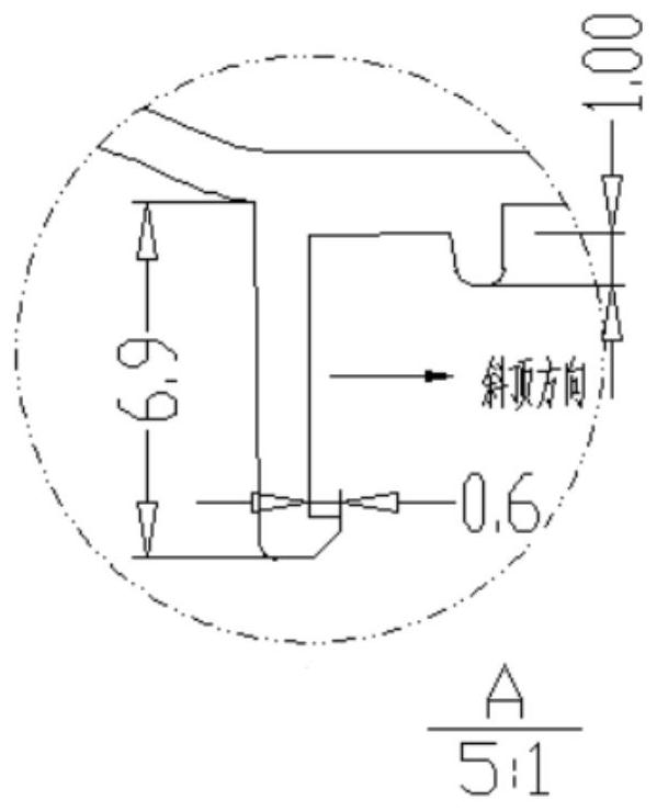

PUM


Abstract

The invention discloses a delayed reverse inclined ejection mold stripping structure and a mold stripping method. The mold stripping structure comprises a straight ejector, an inclined ejector and an inclined ejector base, wherein a straight ejector block is arranged at the top end of the straight ejector; the bottom face of the straight ejector block is connected with the end face of the straight ejector; the area of the bottom face of the straight ejector block is larger than the area of the end face of the straight ejector; a sliding groove is formed in the inclined ejector base; the bottom end of the inclined ejector is arranged in the sliding groove and can slide along the sliding groove; the top end of the inclined ejector makes contact with the bottom face of the straight ejector block; the side face of the straight ejector is fixedly connected with the side face of the inclined ejector base; and the bottom end of the inclined ejector slides along the sliding groove in the inclined ejector base to drive the top end of the inclined ejector to move along the bottom face of the straight ejector block. According to the delayed reverse inclined ejection mold stripping structure provided by the invention, the straight ejector and inclined ejector structure is adopted, and the plasticity of a product is utilized, so that the product deforms in a mold and then is stripped from the mold. The straight ejector and the inclined ejector are driven to move simultaneously through an upper ejector plate and a lower ejector plate, the inclined ejector transversely moves along the bottom face of the straight ejector block while moving upwards to force the product to deform, and when the deformation distance of the product is larger than the back-off distance, the product can be smoothly stripped from the mold.

Description

technical field [0001] The invention relates to a delayed reverse inclined ejection mold structure and a mold ejection method. Background technique [0002] With the increasing development of the plastics industry, plastic products continue to expand and be used more and more widely in various industries, and the structure of the products is becoming more and more complex. There are higher standards for precision fit of molds and dimensional stability. The complexity of the product directly has higher requirements on the stability of the mold structure. How to ensure the simplicity of processing, the convenience of maintenance, and the rationality of the structure while simplifying the structure has become a series of research courses. [0003] The rapid development of science and technology makes the product replacement cycle rapidly shortened, shortening the delivery time and quickly responding to market demand has become the first element for injection mold companies to ...

Claims


Application Information

Patent Timeline
IPC IPC(8): B29C45/44B29C45/40B29C45/26
CPCB29C45/44B29C45/4005B29C45/2602
Inventor 王力
Owner SHANGHAI TIANHAI ELECTRONICS
Learn More