

Automatic exposure method and device
A technology of automatic exposure and area, which can be used in color TV parts, TV system parts, TVs, etc., and can solve problems such as overexposure
- Summary
- Abstract
- Description
- Claims
- Application Information
AI Technical Summary
Problems solved by technology
Method used
Image

Examples
Embodiment 1
[0060] This embodiment will be described from the perspective of a terminal, and the automatic exposure method of the present invention can be implemented by a device with a shooting function such as a terminal.
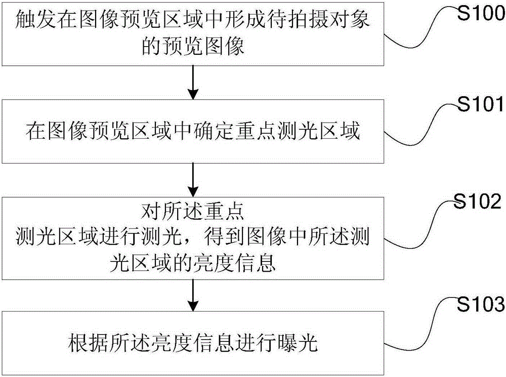
[0061] see figure 1 , figure 1 It is a schematic flowchart of an automatic exposure method provided by Embodiment 1 of the present invention. The automatic exposure method includes the steps of:
[0062] Step S100, triggering the terminal to form a preview image of the object to be photographed in the image preview area.
[0063] In this embodiment, the image preview area is an area for displaying a preview image. For example, after the user turns on the shooting function of the terminal, the area where the preview image is displayed on the shooting interface is the image preview area.
[0064] In this embodiment, the preview image is the image of the object to be photographed displayed in the image preview area of the terminal before exposure. The image of the...
Embodiment 2
[0095] According to the method described in Embodiment 1, an example will be given below for further description.
[0096] In this embodiment, the application of the method in Embodiment 1 to a smart terminal is taken as an example for further description.
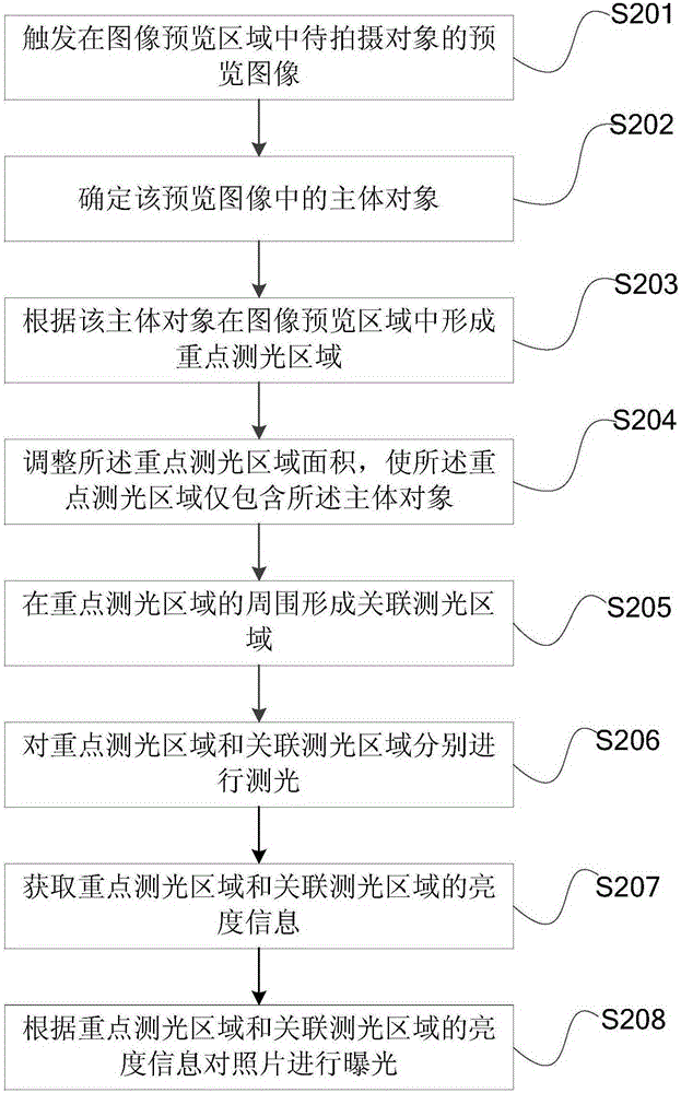
[0097] see figure 2 ,, figure 2 It is a schematic flowchart of an automatic exposure method provided in Embodiment 2 of the present invention. The automatic exposure method includes the following steps:
[0098] In step S201, the smart terminal triggers the formation of a preview image of an object to be photographed in an image preview area.
[0099] For example, when the user turns on the camera function of the smart terminal to take pictures of the scenery, first the smart terminal runs the camera application, calls the camera of the smart terminal to take pictures of the scenery, and displays a preview image of the scenery in the image preview area on the screen.
[0100] Of course, the step of triggering the pre...
Embodiment 3
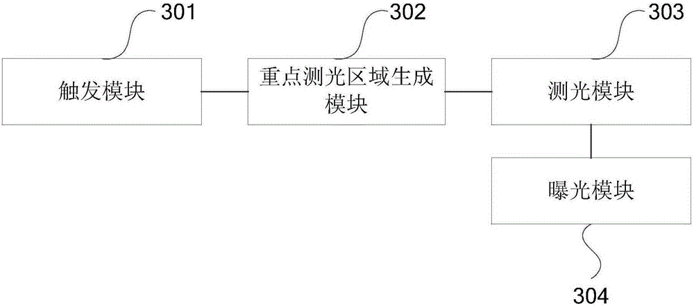
[0130] see image 3 , image 3 It is a schematic structural diagram of an automatic exposure device provided in Embodiment 3 of the present invention. The automatic exposure device includes:
[0131] A trigger module 301, configured to trigger the terminal to form a preview image of the object to be photographed in the image preview area;
[0132] A key photometric area generation module 302, configured to form a key photometric area containing only the main object in the image preview area after determining the main object of the preview image;
[0133] A light metering module 303, configured to measure light on the key light metering area to obtain brightness information of the light metering area;
[0134]The exposure module 304 is configured to perform exposure according to the brightness information.
[0135] Preferably, refer to Figure 4 In this embodiment, the key photometry area generation module 302 specifically includes:
[0136] A key photometric area adjustm...
PUM
 Abstract
Description
Claims
Application Information