Method for operating a transmission device and corresponding transmission device
What is Al technical title?
Al technical title is built by PatSnap Al team. It summarizes the technical point description of the patent document.
A transmission, dual clutch transmission technology, applied in transmission control, elements with teeth, belts/chains/gears, etc., can solve problems such as high current consumption
Active Publication Date: 2016-01-06
AUDI AG
View PDF7 Cites 5 Cited by
Summary
Abstract
Description
Claims
Application Information
AI Technical Summary
This helps you quickly interpret patents by identifying the three key elements:
Problems solved by technology
Method used
Benefits of technology
Problems solved by technology
However this results in higher current consumption
Method used
Image
Click on the blue label to locate the original text in one second.
Reading with bidirectional positioning of images and text.
Examples
Embodiment Construction
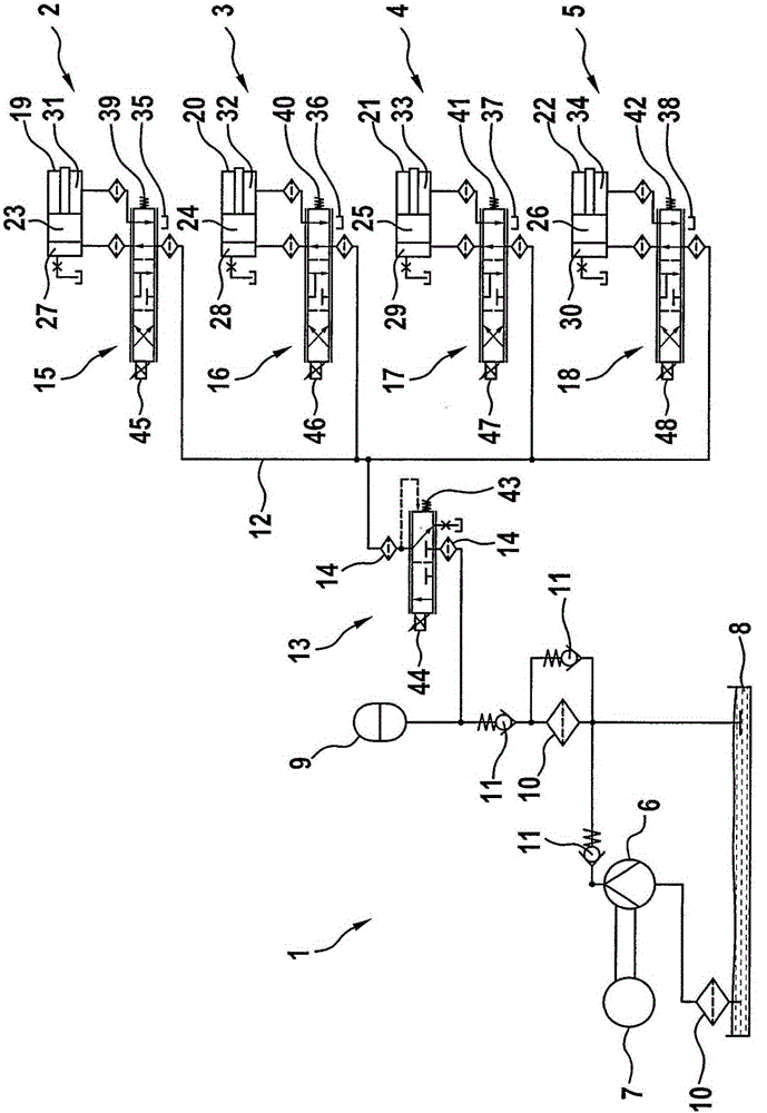
[0028] The drawing is a schematic illustration of a transmission arrangement 1 , which is designed, for example, as a dual-clutch transmission arrangement. The transmission device 1 has a plurality of gear regulators 2 , 3 , 4 and 5 , wherein in principle any number of gear regulators can be provided. In principle, an embodiment with only a single gear selector is also conceivable. Particularly preferably, however, at least two gear regulators are provided. The gear regulators 2 , 3 , 4 and 5 are associated with a common pressure source 6 , for example in the form of a delivery device. The conveying device is driven, for example, by means of an electric motor 7 and serves to convey hydraulic fluid from a tank 8 to the gear shifters 2 , 3 , 4 and 5 . The pressure source 6 can be associated with a pressure tank 9 in which hydraulic fluid under pressure can be supplied even if the pressure source 6 supplies only a low pressure for a short time. A filter 10 can be arranged betw...
PUM
Abstract
The invention relates to a method for operating a transmission device (1), in particular a double-clutch transmission device, the transmission device (1) comprising a plurality of gear selectors (2, 3, 4, 5) each having a gear selector valve (15, 16, 17, 18), and a gear selector piston (23, 24, 25, 26) which is operatively connected to a selector fork of the transmission device (1), is arranged in a gear selector cylinder (19, 20, 21, 22) and divides the latter into a first pressure chamber (27, 28, 29, 30) and a second pressure chamber (31, 32, 30 36). In a first shifting position of the gear selector valve (15, 16, 17, 18), the first pressure chamber (27, 28, 29, 30) has a flow connection to a common feed line (12), in a second shifting position, the second pressure chamber (31, 32, 33, 34) has a flow connection to a common feed line (12), and in a neutral position, none of the pressure chambers (27, 31; 28, 32; 29, 33; 30, 34) has a flow connection to a common feed line; and a flow connection of the feed line (12) to a common pressure source (6) is enabled in a first operating position of the shifting valve (13) and is interrupted in a second operating position of the shifting valve (13). Here, according to the invention, to achieve a change from a standby operating mode into a power saving operating mode, a pressure test is carried out, in which the gear selector valves (15, 16, 17, 18) of the gear selectors (2, 3, 4, 5) for setting the neutral position and the shifting valve (13) for setting the second operating position are activated, and then the gear selector valve (15, 16, 17, 18) of at least one of the gear selectors (2, 3, 4, 5) for setting one of the shifting positions is activated.
Description
technical field [0001] The invention relates to a method for operating a transmission arrangement, in particular a dual clutch transmission arrangement, wherein the transmission arrangement has a plurality of gear regulators, each of which has a gear regulator valve and a shifter with the transmission arrangement. a gear regulator piston operatively connected to the gear shift fork, which gear regulator piston is arranged in the gear regulator working cylinder and divides the gear regulator working cylinder into a first pressure chamber and a second pressure chamber, wherein In the first switching position of the range regulator valve the first pressure chamber is fluidly connected to the common supply line, in the second switching position the second pressure chamber is fluidically connected to the common supply line, while in the neutral position there is no pressure The chambers are fluidly connected to a common input line, the fluid connection of the input line to the comm...
Claims
Application Information
Patent Timeline
Application Date:The date an application was filed.
Publication Date:The date a patent or application was officially published.
First Publication Date:The earliest publication date of a patent with the same application number.
Issue Date:Publication date of the patent grant document.
PCT Entry Date:The Entry date of PCT National Phase.
Estimated Expiry Date:The statutory expiry date of a patent right according to the Patent Law, and it is the longest term of protection that the patent right can achieve without the termination of the patent right due to other reasons(Term extension factor has been taken into account ).
Invalid Date:Actual expiry date is based on effective date or publication date of legal transaction data of invalid patent.