Vibrating mechanism used for powder adding machine

A vibrating mechanism and vibrating bar technology are applied in the shape of heating elements, manufacturing tools, workpiece clamping devices, etc., which can solve the problems of difficulty in adding powder, improve, and difficult to place vibrating bars, so as to improve work efficiency and improve Use effect, effect of improving safety performance

Active Publication Date: 2016-01-13
SANLIAN PUMP IND CO LTD
View PDF9 Cites 0 Cited by
  • Summary
  • Abstract
  • Description
  • Claims
  • Application Information

AI Technical Summary

Problems solved by technology

[0002] During the production process of the electric heating tube, the heating tube needs to be filled with magnesium powder, and the heating tube needs to be shaken when filling the magnesium powder. At present, most enterprises fix the heating tube on the vibrating bar to realize shaking and compacting of the magnesium in the heating tube. Powder, at this stage, most of the heating tubes are fixed on the vibrating bar of the powder feeder by simple binding and fixing. This kind of fixing method is mostly not easy to fix and stable, and because the heating tubes have different models and sizes, it is difficult to achieve a stable position on the vibrating bar. placed, it is not easy to add powder
And because the fixing reliability is not high, most of the current vibrating bars use a single vibrating bar bundled with a single electric heating tube to add powder, which is not conducive to the improvement of production efficiency

Method used


Image

  • Vibrating mechanism used for powder adding machine
  • Vibrating mechanism used for powder adding machine
  • Vibrating mechanism used for powder adding machine

Examples


Embodiment Construction

[0013] The present invention will be further described below in conjunction with accompanying drawing.

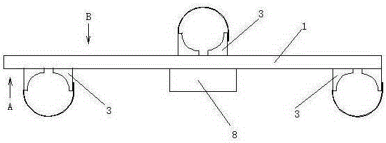
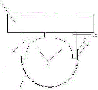
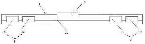
[0014] A vibrating mechanism for a powder feeder, comprising a vibrating bar 1, wherein the top and bottom of the vibrating bar 1 are provided with a slideway 2, including a top slideway 21 and a bottom slideway 22, and the bottom slideway 22 is provided with There are two clamping mechanisms 3, the two clamping mechanisms 3 are arranged at the two ends of the bottom slideway 22, and a clamping mechanism 3 is arranged on the top slideway 21, and the clamping mechanism 2 is located at The middle position of the top slideway 21, the clamping mechanism 3 includes two clamping blocks 31, 32, the clamping blocks 31, 32 are slidably connected on the slideway 2, and the two clamping blocks It includes a first clamping block 31 and a second clamping block 32, which are symmetrically arranged left and right. The clamping blocks 31, 32 are in a square structure, and the clamping bloc...


PUM


Abstract

The invention provides a vibrating mechanism used for a powder adding machine. The top and the bottom of a vibrating bar are each provided with a slide way. The slide ways comprise the top slide way and the bottom slide way. The bottom slide way is provided with two clamping mechanisms which are arranged at the two ends of the bottom slide way. The top slide way is provided with a clamping mechanism which is located in the middle of the top slide way and comprises two clamping blocks. The clamping blocks are connected to the top slide way in a sliding manner. The two clamping blocks comprise the first clamping block and the second clamping block which are symmetrically arranged in a left and right manner. Each clamping block is of a square structure and provided with an arc-shaped groove. A fixing belt is connected to one side of the exterior of the first clamping block. A snap fastener is arranged at the top end of the fixing belt. A snap fastener is arranged on one side of the exterior of the second clamping block. The fixing belt is connected with the second clamping block through the snap fasteners. A motor is arranged at the bottom of the vibrating bar, and therefore a plurality of heating pipe fixing mechanisms are added while heating pipes are effectively clamped, powder can be added to three heating pipes at the same time, work efficiency is improved, and safety performance is improved.

Description

technical field [0001] The invention relates to a vibrating mechanism, in particular to a vibrating mechanism for a powder feeding machine. Background technique [0002] During the production process of the electric heating tube, the heating tube needs to be filled with magnesium powder, and the heating tube needs to be shaken when filling the magnesium powder. At present, most enterprises fix the heating tube on the vibrating bar to realize shaking and compacting of the magnesium in the heating tube. Powder, at this stage, most of the heating tubes are fixed on the vibrating bar of the powder feeder by simple binding and fixing. This kind of fixing method is mostly not easy to fix and stable, and because the heating tubes have different models and sizes, it is difficult to achieve a stable position on the vibrating bar. Placement, it is not easy to carry out the work of adding powder. And because the fixing reliability is not high, most of the current vibrating bars use a ...

Claims


Application Information

Patent Timeline
Patent Type & Authority Applications(China)
IPC IPC(8): B25B11/00H05B3/52
Inventor 孟斌
Owner SANLIAN PUMP IND CO LTD
Why Eureka
Try Eureka