Application method of automobile headrest adjusting structure

A technology for adjusting structure and car headrest, applied in special positions of vehicles, vehicle seats, vehicle parts, etc., can solve the problems of unstable output power, exerted force, neck injury of passengers, etc., and improve the riding comfort. degree, prolong the service life, and ensure the effect of stable performance

Inactive Publication Date: 2016-01-13
成都云科新能汽车技术有限公司
View PDF7 Cites 0 Cited by
  • Summary
  • Abstract
  • Description
  • Claims
  • Application Information

AI Technical Summary

Problems solved by technology

Common active headrests on the market are generally of purely mechanical structure, and there are two main types. One is to rely on the relative movement of the occupant and the seat to push the link mechanism connected with the headrest, and then push the headrest close to the occupant's head, such as SAAB Active headrest, during the collision process, the occupant presses the seat backward due to inertia, and activates the headrest through the space linkage mechanism. The response time of the pillow mechanism is long, that is, the whiplash injury has occurred before the headrest takes effect; the second is that the headrest is triggered by the collision energy, which is driven by a spring. Although the movement of the headrest mechanism is reversible, it cannot be retracted by itself and requires an external Apply force to reset it, the operation is cumbersome, and the intelligent active safety system cannot be used; and during the movement of the headrest mechanism, the output end of the power drive device will be damaged due to special circumstances such as the driving state of the vehicle or its own motion loss. The output power is unstable, that is, the head restraint mechanism has an intermittent sense of frustration. In this case, once a collision occurs, the moving head restraint mechanism will cause serious injury to the occupant's neck

Method used


Image

  • Application method of automobile headrest adjusting structure

Examples


Embodiment 1

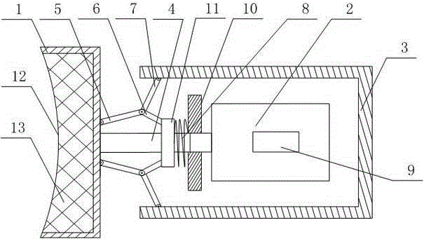
[0026] like figure 1 As shown, this embodiment includes the following steps:

[0027] A First connect the control module electrically connected to the cylinder with the active safety system of the vehicle;

[0028] B When the distance between the vehicle behind the vehicle and the vehicle is within a dangerous range, the control module directly transmits the command to the cylinder, and the output end of the cylinder stretches, so that the adjustment rod drives the headboard to move forward, so that the support of the headrest The part is close to the occupant's head, so as to limit the backward movement of the head relative to the upper torso in the event of a rear-end collision in advance;

[0029] C. During the movement of the head plate, a fixed block is installed on the adjustment rod, and connecting rod A, connecting rod B, and connecting rod C are arranged on the fixed block, the bottom surface of the head plate and the inner wall of the frame, so that the movement of ...


PUM


Abstract

The invention discloses an application method of an automobile headrest structure. The application method comprises the following steps: firstly, a control module electrically connected with a cylinder is directly communicated with an automobile active safety system; when a distance of a vehicle behind to the present automobile is within a dangerous value range, the control module directly transmits a command to the cylinder so that an adjusting rod drives a head plate to move forwards, leading to that a supporting portion of the headrest gets close to the head of a passenger; in the movement process of the head plate, as a fixed block is mounted on the adjusting rod, and a connecting rod A, a connecting rod B and a connecting rod C are arranged on the fixed block, a bottom surface of the head plate and an inner sidewall of the frame, the movement of the head plate is simultaneously supported by the inner walls of the two sides of the frame and the fixed block; when a distance of the vehicle behind the present automobile to the present automobile is within a safe value range, the control module directly controls the cylinder to retract and then head plate directly falls into a rectangular groove so that the head of the passenger and the supporting portion of the head rest return, and therefore, synchronization of headrest protection and the automobile safety system is realized.

Description

technical field [0001] The invention relates to an intelligent automobile active safety system, in particular to a method for using an automobile headrest adjustment structure. Background technique [0002] The forms of traffic accidents are divided into frontal collision, side collision, rear-end collision and pedestrian collision. Among them, rear-end collisions have a high probability of occurrence due to their unpredictability. Therefore, in the study of automobile safety, when planning the protection strategy for the occupants of the vehicle, the rear-end collision in the above-mentioned form, although the fatal injury to the occupants and the serious deformation of the vehicle body are relatively small, it will still cause serious damage to the occupants of the front vehicle. Whiplash to the neck. [0003] In the prior art, the neck protection is mainly based on the seat system. The protection principle is to limit the backward movement of the head relative to the up...

Claims


Application Information

Patent Timeline
Patent Type & Authority Applications(China)
IPC IPC(8): B60N2/48B60N2/427
Inventor 刘力
Owner 成都云科新能汽车技术有限公司
Why Eureka
Try Eureka