Rotary steel pipe clamp capable of automatically arranging pipes

A rotary and management technology, applied in the direction of lifting devices, etc., can solve the problems of high labor intensity and low work efficiency, and achieve the effect of reducing labor intensity, not easy to fall, and improving work efficiency

Inactive Publication Date: 2016-01-13
HEFEI HANDBAROW APPURTENANCES TECH
View PDF8 Cites 9 Cited by
  • Summary
  • Abstract
  • Description
  • Claims
  • Application Information

AI Technical Summary

Problems solved by technology

At present, in the storage process of steel pipes, in order to manage the steel pipes, it is necessary to manually organize them one by one, which is not only labor-intensive, but also low in work efficiency.

Method used


Image

  • Rotary steel pipe clamp capable of automatically arranging pipes

Examples


Embodiment Construction

[0012] The technical solution of this patent will be further described in detail below in conjunction with specific embodiments.

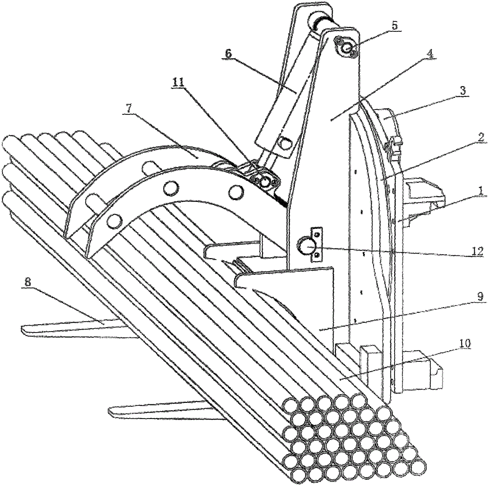
[0013] see figure 1 , a rotary steel pipe clamp for automatic management, including a rotating base 1, a rotating frame 4, pressing teeth 7 and a fork 8; A deceleration motor 3 that drives the rotating frame 4 to rotate is also installed. The slewing bearing 2 is an inner and outer ring structure, and its inner ring and outer ring are respectively connected to the rotating frame 4 and the rotating base 1, so that the rotating bearing 2 makes the rotating frame 4 and the rotating base 1 can rotate relative to each other, and the reduction motor 3 drives the rotating frame 4 to rotate around the rotating base 1. Preferably, the slewing bearing 2 and the reducing motor 3 are fixed on the rotating base 1 by bolts; the fork 8 is fixed on the rotating base 1. At the lower end of the frame 4, the pressing tooth 7 is rotated and installed in the middle of...


PUM


Abstract

The invention discloses a rotary steel pipe clamp capable of automatically arranging pipes. The rotary steel pipe clamp comprises a rotary base, a rotating rack, a pressing tooth and a fork, wherein the rotating rack is rotationally mounted on the rotary base through a slewing bearing; a speed reduction motor for driving the rotating rack to rotate is further mounted on the rotary base; the fork is fixed at the lower end of the rotating rack; the pressing tooth is rotationally mounted in the middle of the rotating rack through a pressing tooth connecting shaft; the pressing tooth cooperates with the fork to form a steel pipe clamping and fixing jaw; a hydraulic oil cylinder for driving the pressing tooth to rotate is further mounted on the rotating rack; a clamping opening in the lower side of the pressing tooth is circular -arc-shaped; a rear collecting box is arranged at the lower part of the rotating rack; the rear collecting box is positioned at the back end of the fork; and a collecting opening in the front side of the rear collecting box is circular -arc-shaped. By adopting the rotary steel pipe clamp capable of automatically arranging the pipes, steel pipes scattered on the ground can be arranged and stacked orderly, and the fact that the steel pipes are arranged manually one by one is not required, so that the labor intensity of workers is reduced, in addition, the working efficiency is improved and increase of enterprise benefits is facilitated.

Description

technical field [0001] The invention relates to a steel pipe clamp, in particular to a rotary steel pipe clamp for automatic management. Background technique [0002] The development of steel pipe production technology began with the rise of the bicycle manufacturing industry, the development of petroleum in the early 19th century, the manufacture of ships, boilers, and aircraft during the two world wars, the manufacture of thermal power boilers after the Second World War, the development of the chemical industry and Drilling, production and transportation of oil and natural gas have strongly promoted the development of steel pipe industry in terms of variety, output and quality. The steel pipe is used to transfer fluid and powder, exchange heat and produce mechanical parts and containers, what's more it's a kind of economical steel. Using steel pipes to manufacture building structure grids, pillars and mechanical supports can reduce weight, save metal by 20-40%, and realiz...

Claims


Application Information

Patent Timeline
Patent Type & Authority Applications(China)
IPC IPC(8): B66F9/06B66F9/14B66F9/18B66F9/22
Inventor 包训权崔怀金
Owner HEFEI HANDBAROW APPURTENANCES TECH
Why Eureka
Try Eureka